4¼-inch Telescope of Long Focus
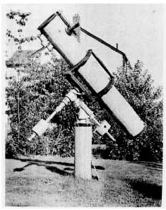
Almost everything that has been said of the 6-inch can be applied to a 4¼- inch, a size of reflector which seems to have been considerably underrated. It is the regrettable truth that vast numbers of large and excellent telescopes are collecting cobwebs in attics, garages, and cellars, simply because they are too massive lo be readily moved outdoors and in. No doubt their owners were once enthusiastic amateur astronomers, but their ardor has been dampened, and they have been denied many anticipated pleasant evenings of observation, because a too-ambitious program was undertaken as an initial venture. The 4¼-inch reflector is a powerful instrument in its own right, far more telescope than Galileo ever had. Including a tripod, its total weight is trifling, between 20 and 30 pounds. At f/10 and over, the mirror can be finished spherical. If you are after magnification, this size can be made f/15, at which ratio it will compare in performance to a refractor of similar dimensions. The parts for the mounting of a 414-inch, of ratio above f/6, should be of the size listed under “A,” Table I.
Larger Instruments
A telescope larger than the 6-inch can hardly be made portable, as that term is generally understood. Of course, the mounting can be placed on a tripod, to permit moving it about, but the handling may not be easy. A possible exception is an 8-inch f/4 or f/4.5, which can be carried on the mounting shown in Fig. 73.

selection of fittings for larger and permanently mounted telescopes is left to the discretion of the amateur, but remember that to make this an extremely rigid assembly. Bearings of similar design are used in the 8-inch telescope mounting illustrated in Fig. 96. For roughing out the curve on moderate-sized mirrors, No. 80 carbo may be considered about as fast as the coarser No. 60, and it does not result in as deeply pitted a surface. But for 8-inch mirrors of f/6 and lower ratio, and on all large mirrors, it will be more economical to do the excavating with No. 60. Grinding may then proceed with No. 80, or a series consisting of Nos. 100, 150, then 220, and so on may be used. As the amount of pressure per unit area of a large mirror can hardly equal that used on a 6-inch, it will take a longer time to grind down each charge of abrasive, and at least the same number of charges of each grade must be used.
|
|
Testing Notes
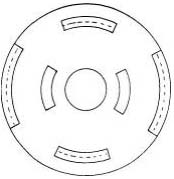
On large mirrors, it is usual to supplement the methods of testing already described with measurements made in several zones. For this purpose, diaphragms with ½” zonal openings (Fig. 97) are used, the mean radius of the openings being taken as the radius of the zone being tested. The central aperture in the mask in Fig. 38a is one quarter of the mirror’s diameter, which is satisfactory for a 6-inch f/8 mirror or higher ratio, but on larger and deeper mirrors this opening should not exceed 20 per cent of the diameter. Zonal testing is somewhat tedious, but nevertheless necessary, as there is too great an area on large mirrors to depend on the eye detecting minute vagaries in shadow appearances without some means of isolating them.
As a useful supplementary test, two or three disks of cardboard may be made, each with a different-sized central opening, the smallest being, perhaps, equal to half the diameter of the mirror. As each such stop is in turn placed before the mirror, a different size of “mirror” of different focal ratio is exposed, and the paraboloidal shadows of each can be examined. If desired, use separate masks, similar to Fig. 38a, for each aperture. Zonal discrepancies will show up under this test about as readily as by the method mentioned above.
|
|
At corresponding settings of the knife-edge, the figures should have similar appearances, except for a difference in the depth of the shadows.
The shadows on an f/4 or f/5 paraboloidal mirror are quite intense, looking somewhat like those of Fig. 33 when the knife-edge is placed at the 50-per-cent setting. Seen on a 6-inch f/8, shadows of this intensity could only accompany a deep hyperboloid. But on an f/8 mirror of larger diameter, where the correction is greater than on the 6-inch, the contrast between highlight and shadow also increases. For a 12-inch f/8, with double the amount of correction of the 6-inch, Fig. 33 might well be an accurate representation of its appearance when parabolic.
Tolerable Knife-edge Error
It has been found that reasonably perfect performance is assured if the mirror’s surface does not vary by more than a quarter of a wave length from a paraboloid. The allowable amount of undercorrection or overcorrection, or the departure in inches from the value of r2/R, for mirrors so figured, is given in Table V. Note that the allowable error varies as the square of the focal ratio. It is independent of the diameter, and therefore applies to mirrors of any size.
Table V. Tolerable Aberration Error in Paraboloidal Mirrors
with Stationary Pinhole at Center of Curvature
|
Focal ratio |
Error in inches |
Focal ratio |
Error in inches |
| f/3 |
0.006 |
f/7 |
0.035 |
| f/3.5 |
0.008 |
f/8 |
0.045 |
| f/4 |
0.011 |
f/9 |
0.057 |
| f/4.5 |
0.014 |
f/10 |
0.070 |
| f/5 |
0.018 |
f/11 |
0.087 |
| f/6 |
0.025 |
f/12 |
0.101 |
For Newtonian telescopes, the above theoretical tolerances may be taken to the nearest hundredth of an inch, but because of probable testing errors, which may amount to as much as 0.02″, it is advisable to reduce the allowable knife-edge error where possible by up to that amount. It is evident therefore that mirrors of f/6 and lesser ratio must be very precisely figured. (See, however, considerations mentioned on page 171.) High-ratio mirrors, for which the tolerable aberration error exceeds the value of r2/R, may be left with a spherical figure. For example, the aberration at focus of a spherical mirror may be very closely approximated from the value of r2/4R, which for a 6-inch f/11 will amount to 0.017″. But if, in figuring, full advantage were taken of the tolerance given in Table V, the mirror’s aberration at focus would then be 0.022″ (0.087/4). The spherical 6-inch f/11 mirror is thus seen to lie well within a quarter wave of a paraboloid.

