Extra-focal Diffraction Rings
By moving a high-power eye-piece inside or outside of focus, a bright star image will be seen to expand into a luminous disk which can be resolved into a number of concentric rings, atmosphere permitting. To the initiated eye, these extra-focal rings tell the story of the optics of the telescope. Half a dozen or more may be visible, the outer one being the widest and brightest, and the inner rings diminishing in brightness inwardly (somewhat like a reversal of Fig. 53b). With a perfect mirror, the appearance of the rings will be identical at equal distances either side of focus. (Visual tests will be upset if spherical aberration is present in the eyepiece.) If, outside of focus, the inner rings are brighter than when viewed inside of focus, undercorrection of the mirror is indicated; overcorrection, if a reverse condition is found. In a reflector, a dark area will be observed at the center of the expanded pattern, the innermost rings being obscured by the secondary mirror.
Each ring should appear uniformly bright; if the rings are brighter on one side, the alignment is at fault. At a small distance inside or outside of focus, where only two or three rings are visible, the outer one having considerable thickness, examine closely for any departure from roundness. If the rings are triangular, or have some other odd shape, there is strain or flexure in the mirror. If oval-shaped rings are seen, astigmatism is present, which may be in the eye, eyepiece, or either of the mirrors. Push the eyepiece to the other side of focus, to see if the elongation is then at right angles to the first position — this will relieve the eye of suspicion. If the elongated rings remain unchanged as the eyepiece is rotated in the adapter tube, the eyepiece is eliminated. Rotating the mirror in its cell will then isolate the source of the trouble. A diagonal of poor figure or one pinched in its holder can cause an astigmatic image.

At best focus, one diffraction ring should be visible around a bright star image (Fig. 86). When the seeing is poor, the ring (if at all visible as such) will appear to rotate and perhaps waver to such an extent as to merge with the central disk, at which times the star image may appear as an indefinable splash of light. But with the smaller aperture had by using the diaphragm of Fig. 87, the rings, both in and out of focus, will almost always be seen around any bright star image and, coming from a stopped-down mirror of such relatively high ratio, can be used as a criterion of perfection.
The same diaphragm may be effectively used in viewing such trying objects as the full moon or the planet Venus. It is especially helpful for terrestrial observation, permitting the use of a low-power eyepiece with its large field of view, since there is then no objectionable shadow from a secondary mirror, and it also permits of observations on nights when the atmosphere is in such turmoil as to preclude the use of full aperture.
|
|

Atmosphere, and Thermal Disturbances
The most annoying abomination to plague the amateur astronomer, next to mosquitoes and frostbite, is turbulence in the atmosphere. In general, the atmosphere is built up of layers of air of different temperatures and densities, and therefore of different refractive indices. These layers may stream along like vast invisible rivers in different directions, rippling and undulating, sometimes rising or descending with rushing force. Local topography, nearby mountains, woodland, and the presence of large bodies of water exert an influence on these turbulences, which may change from hour to hour. It is small wonder that seeing is frequently poor when one considers that the starlight entering a telescope has been buffeted about in its passage through these layers of differing indices. The effects are particularly worsened if the star’s altitude is low, the seeing declining rapidly below an altitude of 40°.
Some localities have a large annual percentage of nights when the seeing is good, and high magnifications can be consistently enjoyed. Such places are preferred as sites for observatories. In the arid regions of the West, for example, large telescopes perform better than along the Atlantic seaboard, where the seeing is not very good. But even the poorest regions in this respect have their share of nights when the atmosphere seems to be perfectly still, and the highest magnifications can be used. In the East, best conditions prevail during the summer months. It is commonplace then, in testing the seeing by observing the closer pair (separation 2.5 seconds of arc) of the quadruple star, Epsilon Lyrae, to find the images quite stationary, each disk perfectly defined and surrounded by its diffraction ring. But with the coming of fall, conditions change. In contrast, then, the diffraction disks appear to be doing a dance, and only in momentary glimpses can the diffraction patterns be made out. Hazy nights, while they cut down on the transparency, are usually very good, the tiny droplets of water suspended in the atmosphere evidently acting as ballast. Especially poor are the transparent “sparkling” nights of winter, when Sirius may sometimes be seen to twinkle in all the colors of the spectrum.
Both refractor and reflector are subject to these observing hindrances, and there is nothing that can be done about them. But the reflector sometimes has the disadvantage of thermal disturbances inside its open tube. How to control them effectively has long been a problem. Heating units, mechanical ventilation, insulation, and other devices have been tried with more or less success. One form of disturbance is air flowing along the walls of the tube, just as tobacco smoke creeps along a table top. This could be overcome by use of a tube an inch or more greater in diameter than the mirror. But if the tube is taken outside and ventilated about an hour before observations are scheduled to commence, these currents should be swept away. As we shall see, this should be done anyway. It is the practice followed by the author, and I have never encountered any thermal difficulties of this sort inside the tubes of the telescopes shown in the frontispiece and in Fig. 96, both of which are lined with sheet cork.
Properly installed, the sheet-cork lining should be made to hold itself by compression inside the metal tube, without need for retaining rings; the width to which the sheets of cork must be cut should therefore be predetermined by experiment. Consider the case of lining an aluminum tube 56″ long, outside diameter 7″, wall thickness 1/16″, with sheet cork 1/8″ thick. The inner circumference of the tube is 21.6″, and when lined will be reduced to 20.8″, which would suggest that the width of the sheets ought to lie somewhere between these two figures. By experiment with a scrap length of the material, it will be found that the snuggest possible fit can be effected with a width of 21 5/16″. Accordingly, cut to this width two sheets of cork, one 37″ and the other 19″ in length. Locate and cut out holes for the spider arms, eyepiece opening, and so forth, and paint dead black the surfaces to be exposed. Then bend each sheet into a curved “W” shape, and push each separately into its position in the tube, with all edges meeting in butt joints. The bulge should be left opposite the seam, as in Fig. 88, and it is then to be carefully pressed out.

Emphasis has often been placed on the necessity of ventilating the mirror end of the tube at all times, but under certain conditions this does not work out to advantage while actually observing. With the telescope in Fig. 96, heated air rising from the ground has on occasion been found to be passing through the tube, causing a boiling of the image, and this was effectively arrested by fitting a tight cover over that end and keeping it there for the duration of the observations.
The principal reason for giving the telescope ample time for ventilation before observing is to allow the mirror and metal parts to become adjusted to the temperature of the outside air. It has long been known that changing temperature within the substance of the mirror is deleterious to definition. In an effort to observe what takes place while the mirror is adjusting itself to the temperature of the surrounding air, the author experimented with five pyrex mirrors, four of them being excellently figured paraboloids, and one having a spherical figure. These were immersed on different occasions in warm water (96° F.) and cold water (46° F.) for half-hour periods, and subjected to the Foucault test following each immersion, in a room having a temperature of 68° F. These temperature differences, 28° and 22° respectively, are believed to be no greater than may be frequently encountered by the amateur and his telescope. The results of the tests are given in Table III. The third column lists the measured corrections present on the mirrors upon removal from the warm water; the fifth column, the corrections measured upon removal from the cold water. In the fourth and sixth columns are the elapsed times before the mirrors returned to their normal corrections given in the second column.
TABLE III
|
Size of Mirror |
Normal corr. (r’/R) |
Cooling |
Return to normal |
Warning |
Return to normal |
|
6″ f/4 |
0.18″ |
0.18″ |
……… |
0.18″ |
……… |
|
6″ f/8 |
0.09″ |
0.14″ |
25 min. |
Spherical |
30 min. |
|
8″ f/5 |
0.20″ |
0.21″ |
……… |
0.20″ |
……… |
|
8″ f/8 |
0.13″ |
0.19″ |
35 min. |
0.05″ |
30 min. |
|
6″ f/9 |
Spherical |
Ellipsoid (0.07″) |
30 min. |
Oblate |
30 min. |
Apparently the figures of mirrors of low focal ratio are little affected by changing temperature, whereas the change in figure of those of high ratio may be pronounced. In testing the f/8’s and the f/9, the knife-edge had to be constantly shifted to keep pace with the continually changing figures. And at intervals, far beyond the time required for the figures to return to normalcy, the air in front of each mirror would boil and seethe with convection currents, indicating that for a considerable period satisfactory observing might be difficult.
The findings in the third column of Table III represent the conditions prevalent to a more or less degree in the lowering temperatures of nightfall, when the amateur most frequently undertakes observations, but it should be noted that the difference of some 28 degrees to which the experimental mirrors were subjected was abrupt. In practice, a gradual change of 5° per hour might be encountered, which will hardly affect performance. But sudden changes, as when the telescope is brought out from a warm room, are not conducive to best results.
It might be added, parenthetically, that any zonal errors present on a mirror (above f/5) will stand out in bold relief if subjected to the hot-water treatment and then given the knife-edge test.
Because of the larger cylinder of air through which the light from a star must pass to reach the mirror, a large telescope has little chance of performing up to the theoretical limit of its resolving power. It is frequently found necessary, in order to continue observations, to diaphragm large telescopes down to a smaller aperture and thus to diminish the effects of atmospheric turbulence.
|
|

The Limiting Visual Magnitude of a Telescope
The early Greek astronomers, Hipparchus and Ptolemy, classified the stars in order of brightness. The brightest stars were designated as 1st magnitude, and those just bordering on the limit of visibility as 6lh magnitude. John Herschel found that a lst-magnitude star was on the average about 100 times brighter than one of the 6th magnitude, and that there was a geometrical progression in the scale, stars of any given magnitude being about 2½ times as bright as those of one magnitude lower. This ratio has now been fixed at the number whose logarithm is 0.4, or very nearly 2.512. A standard lst-magnitude star (lm.0) is 2.512 times brighter than one of 2ra.O, 2.5122 (or 6.3) times brighter than one of 3m.0, 2.5123 (15.8) times brighter than one of 4m.O, and so on. On this scale, a standard lst-magnitude star is about 25,000 times as bright as one of the 12th magnitude.
The limiting visual magnitude of the naked eye, with a papillary aperture of about 7 mm., is somewhat better than 6m.O (some eyes can detect stars of 7m.0). Since the light grasp of a telescope is proportional to the square of its aperture, a 1-inch telescope should therefore reveal stars of about the 9th magnitude. On this basis, which lias been generally adopted, Fig. 89 has been prepared, showing graphically the approximate limiting magnitude for telescopes of different apertures.
Aberrations of the Paraboloid
Definition on the axis of your paraboloidal mirror should be limited only by diffraction. That is the property of the paraboloid, and at any focal ratio perfect images will be found on axis. Used photographically, for the recording of nebulae and clusters, seldom exceeding in diameter about 20 minutes of arc, your mirror should give practically perfect results. This is because the diameter of the image of a star on the plate within that limited field will easily exceed the size of the off-axis aberration image. But the farther off axis the image is placed, the more it is affected by the aberrations discussed in this section. The considerations presented here should be carefully weighed in planning a second telescope (see the next chapter) or in adapting the first one for photography. The principal advantage of a wide-aperture telescope lies in its light-gathering power, and if it is of low focal ratio its speed makes it most useful for photographing faint nebulae and clusters.

The most serious off-axis aberration is coma, which gives star images an “opened-parachute” shape, pointing toward the axis (Fig. 90). This elongation, often seen in the images of outlying stars on photographs, and visually conspicuous in a 6-inch f/5, may be several times the size of the theoretical diffraction disk, the effect of the aberration increasing with the distance from the axis, and as the inverse square of the focal ratio. (The amount of image spread can therefore be lessened by diaphragming the mirror, and so decreasing its angular aperture.) The length and width of the comatic image are in the ratio of 2 to 3, with an unequal distribution of light in it, the greatest intensity being at the point. There is no way of knowing where in this fan-shaped image blur the star is supposed to be, and there is no compromise of focus where a round star image can be had. Table IV gives the length of a star image afflicted with coma at various distances from the axis.
TABLE IV
Angular sizes (in seconds of arc) of star images due to coma in variously proportioned mirrors, at given distances (in minutes of arc) from the axis.
|
Focal ratio |
5′ |
15′ |
30′ |
|
f/4 |
3″.44 |
10″.31 |
20″.62 |
|
f/6 |
1.54 |
4.62 |
9.24 |
|
f/8 |
0.87 |
2.62 |
5.24 |
|
f/10 |
0.55 |
1.65 |
3.30 |
|
f/12 |
0.39 |
1.18 |
2.37 |
|
f/15 |
0.25 |
0.74 |
1.48 |
It is seen that the field of good definition of a paraboloid is rather small, hardly half a degree in moderate focal ratios, and extremely limited in an f/4. For relative freedom from this aberration, the mirrors should be constructed in proportions usually assigned to lenses.
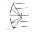 |
Fig. 91. Coma in a paraboloid.
Of secondary importance is the astigmatism of off-axis images (not to be confused with astigmatism from an unsymmetrical mirror, which affects axial images as well), the aberration increasing with the square of the image distance from the axis. Whereas in coma (Fig. 91) the points of focus of the different zones of the mirror are not concentric, astigmatism arises from the failure of rays from different parts of the same zone to intersect in the same plane. The dotted circle in Fig. 92 represents a zone on the mirror surface. Oblique rays (dotted lines) reflected from points A and B on the mirror intersect at a, and the rays from C and D intersect at c. The image at a, instead of being a point, is a straight line perpendicular to the plane of the oblique rays, and the image at c is also a straight line, but at right angles to that at a. In the absence of coma, a symmetrical image, located in the circle of least confusion, may be found on the focal surface (dotted line intersecting the mirror’s axis). A short distance inside or outside of focus, the image should be in the shape of an ellipse.
|
|

Because of the presence of these oblique aberrations, it must not be thought that the reflecting telescope is an inferior instrument. The same aberrations exist to a greater or lesser degree in most optical systems, although in the case of the achromatic doublet, coma can be quite completely eliminated through a suitable choice of lens curvatures. With the simple paraboloidal mirror, no such freedom of off-axis aberration is possible. Professional astronomers and advanced amateurs, seeking reflectors with wide fields of good definition for photography, turn to the Schmidt-type telescope, in which an aspherical correcting plate or lens is used in conjunction with a spherical mirror.