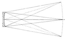
Rays of light from a distant star, upon reaching the earth, are sensibly parallel, and the rays that strike the surface of our paraboloidal mirror are contained in a cylinder 6″ in diameter. They are then converged by reflection to form a point image of the star at the focus of the mirror. If a strip of screen is stretched across the focus, and if other stars are present in the field, their images will be observed on the screen extending a number of degrees on either side of the optical axis. The focal surface thus formed is not actually flat, but is a section of a sphere, concave toward the mirror (Fig. 44). But all the star images will not be of equal quality, and only the one that lies on the axis will be perfect. Because of the oblique aberrations known as coma and astigmatism (see Chapter 18), present to a greater or lesser degree in most optical systems, the images deteriorate as they lie farther from the axis, with the result that only a very small part of the field is fit for useful study.
|
|
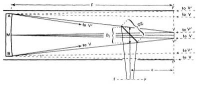
In order to deflect this useful field to one side, so that the observer will not obstruct the incoming rays, a secondary mirror or diagonal is placed a short distance inside of focus, at an angle of 45°. The optical axis is thus deflected by 90°, and the rays from the primary mirror are diverted to form the image in the secondary focal plane (see Fig. 47). The plane reflecting surface of the secondary may also be produced by total internal reflection from a right-angle prism. We shall briefly discuss the merits of a prism and then consider the dimensions of the diagonal mirror called for in the standard design we have adopted.
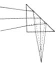
The objections to a prism diagonal are its greater cost and difficulty of mounting, and the fact that it must necessarily offer a four-cornered obstruction to the light. The glass prism surfaces are easier to keep clean than the aluminized surface of the diagonal, and so are more enduring. In reflective ability both are, ordinarily, about equal. At the 45° angle, the aluminized diagonal reflects about 90 per cent of the light coming from the mirror. Normally, the entrance and exit faces of the prism reflect about four per cent (the hypotenuse face is internally totally reflecting), and there may be a loss of about two per cent due to absorption; about 90 percent of the original light is therefore transmitted by the prism. However, if its entrance and exit faces are given an anti-reflection fluoride coating, the losses there will be reduced to a fraction of one per cent, and there is then no question of the superior reflectivity of such a prism.
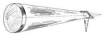
When a prism is employed, refraction of the converging rays at both of its faces will cause an outward displacement of the focal plane, as shown in Fig. 45. For crown glass of refractive index 1.5, this displacement amounts to one third of the total path length of the axial ray through the prism. (Of course, no axial ray actually enters into the image, as it is obstructed by the prism.)
How Large a Diagonal?
Whereas each point image in the primary focal plane would be illuminated by the full aperture of the mirror (in the absence of the tube), only a part of the secondary plane surrounding the axis will receive the benefit of full aperture, the size of the fully illuminated field there being governed by the size of the diagonal. Fig. 46 illustrates the convergence of rays by the mirror to form a single point image on the axis. It can be seen that, wherever the diagonal is placed in that cone of rays, the plane of the cone intersected by its reflecting face is in the shape of an ellipse. As the angle is 45°, the lengths of the minor and major axes of the ellipse may, for all practical purposes, be regarded as in the proportion of one to the square root of two, or 1 to 1.4. The diagonal may be either rectangular in shape, which is simplest to make but needlessly obstructs light and introduces added diffraction, or elliptical. If rectangular, the shape of the diagonal obstruction, when viewed from a point on the axis, is that of a square; if elliptical, the apparent shape is circular.
|
|
The need for secondary reflection in the Newtonian telescope has its analogy in the star diagonal of the refractor. This is usually a prism placed a little distance ahead of the focal plane to deflect the image to a more comfortable viewing position. The prism is of such size as to permit the unobstructed passage of rays from the objective to all parts of the largest field to be viewed. This field, measured linearly, is of approximately the same diameter as the field lens of the lowest-power eyepiece. For a starter we might try applying the same reasoning to the problem of the size of the Newtonian diagonal.
In general, the least power that will be used on the reflector will be had from an eyepiece of l½” focal length, the field lens of which will be about 1″ in diameter. Accordingly, a field of view of this size, VV in Fig. 47 (not drawn to scale), is marked off, V2″ on either side of the optical axis, in the primary focal plane FP. The angular size of this field, VMV, can be found as follows: An arc of a circle equal in length to the radius, and called a radian, subtends an angle of 57°.3. As the focal length of the mirror, 48″ for the 6-inch f/8, is the radius here involved, a 1″ length of the arc will contain 1°.2, or 72 minutes of arc. Two stars that are separated by this angular distance may be imaged at V and V, and can just be fitted into the field of view of the low-power eyepiece. If the principal rays MV and MV have been drawn, only two more rays, AV and BV, need be added to complete the representation of image formation of the two stars. (To avoid confusion in the diagram from the use of many lines, rays BV and AV are shown in part.) The truncated cone ABVV is thus seen to contain all the rays that flow from the mirror to illuminate every point within the field VV.
|
|
The location of the diagonal inside this cone must now be established, and it is obvious that the closer it is to the focal plane the smaller it can be. With a well-designed focusing eyepiece holder, the distance of the secondary focal plane (fp) outside the tube can be kept at a minimum, about 1^”. But the amateur, using a telescoping drawtube and a bulky support, will require about 3″, which added to the radius of the tube (next to be established) gives the distance inside of focus for the diagonal.
Now, it is desirable for constructional reasons to have the tube extend to the primary focal plane, where the oblique rays FA and PB, proceeding from points on the edge of the wide field, are found to be 3½” distant from the axis of the mirror. Evidently, then, the inside diameter of the tube need be no larger than 7″. But what if it is smaller, as is the case with the aluminum tube shown in the frontispiece? That tube has an outside diameter of 7″, with a wall thickness of 1/16″, and a cork lining l/8″ thick. It therefore intrudes 3/16″ into those field rays, obstructing a peripheral zone of similar width on the mirror, resulting in an insignificant loss of illumination at the edges of the field of the low-power eyepiece. The major portion of the field, ¾° in extent, is unaffected. With higher-power eyepieces, which may take in a field of this size or less, there is no hindrance by that tube. Actually, the inside diameter of the tube may be as little as 6½”, but it should not be less than that, as some space must be provided around the mirror to allow ventilation.
The position of the diagonal inside the focal plane is now fixed, in this case, at 6½” (the radius of the tube plus the distance outside to fp). That is assumed to be the position of the diagonal in Fig. 47, where D2 is the major axis, and D1 may be taken for the minor axis. These lengths can be measured from a scale drawing; or the width Dj is given by the formula:
 |
where v is the linear width of VV, c is the distance of the diagonal from the focal plane, F is the focal length of the mirror, and M its diameter. D2 multiplied by 1.4 equals D2. This gives, for the above example, a diagonal of dimensions 1.7″ x 2.4″. But in making the analogy with the star diagonal of a refractor, we did not take into account that the diagonal of the reflector is placed in front of the mirror, forming an obstruction to the incoming light. So before adopting the above size, consideration should be given to the effects of a central obscuration.
In Fig. 48, which is not drawn to scale, an elliptical diagonal, forming a circular obstruction, is shown 41½” from a 6-inch f/8 mirror. Parallel rays from an axial star, and from two other stars each 36 minutes of arc distant from the axis, are shown approaching the mirror. For the axial star a central area of the mirror equal in size to the area of the obstruction is blocked off. For the field stars, overlapping areas of similar size are also obstructed. It is seen that a small central area of the mirror, the black spot in the diagram, will never be used. Furthermore, the gray zone, a trifle more than 2/5″ wide when the low-power eyepiece is used, contributes only to the edge of the field of that low-power eyepiece. In the case of a single star at the edge, less than half of the gray zone is used.
|
|
The black spot is relatively larger for higher-power eyepieces, and for an eyepiece of 14″ focal length, which takes in a very much smaller field, the unserviceable part of the mirror expands to a diameter only Vs” less than that of the gray zone. Thus, the mirror maker now realizes that he need not be unduly alarmed about surface defects of any nature in a central area of the mirror of diameter about equal to the width of his diagonal. This also explains why there is no loss in perforating the primary when a Cassegrainian telescope is made.
As the reader may demonstrate to his own satisfaction, these findings regarding the proportions of the centrally obstructed areas apply to any size mirror, of any focal ratio, for linear fields of view of similar diameter (about 1″). Small variations in the width of the gray zone occur as a result of relative differences in the distance of the diagonal inside of focus.
Thus it is seen that the larger the diagonal, the less light there is in the image. More serious, though, is the diffraction that is introduced. This becomes conspicuous when the area of the obstruction exceeds six per cent of that of the mirror. (See the discussion on diffraction in Chapter 18.) For these reasons, it is important that the size of the diagonal be kept at a minimum compatible with the needs of the observer. The area of the mirror obstructed by a diagonal measuring 1.7″ x 2.4″ is, if rectangular, 10.3 per cent, and if elliptical, eight per cent of the total. The low-power eyepiece for which this size diagonal is designed is used almost exclusively as a “finder”; when the object sought has been located and centered in the field, the observer invariably switches to an eyepiece of higher power. It is not logical, therefore, to saddle the telescope with a lot of light obstruction and harmful diffraction from a needlessly large diagonal.
The larger diagonal may be justified only in the case of a mirror of low focal ratio, designed for use with low power, where a wide field of view is desired for such observations as the exploration of star fields, comet seeking, and so on. Even there (except for the specific case of variable star work, when the tube, too, should not cut off any part of the field) it is most likely that use of a diagonal of, say, l½” in width, of elliptical shape, and obstructing but six per cent of the mirror’s area, would prove far more advantageous than the size prescribed by geometry.
|
|
For our f/8 mirror, a minimum practical size may be arrived at from the fact that its field of reasonably good definition is about 30 minutes of arc in width, about the size of the moon. The linear size of the moon’s image is found in this way: the tangent of 30′ is 0.0087, which, multiplied by 48 (the focal length of the mirror), gives 0.4176″ or about 2/5″ at the focus. Substituting this value for the width of VV, Fig. 47, the size of the diagonal derived from the formula is then, in even fractions, 1 3/16″ x 1 5/8″. Its area of obstruction, if rectangular, is five per cent, and if elliptical, four per cent of that of the mirror. The amount of light obstructed by it is at a near minimum, and diffraction is reduced to the vanishing point.
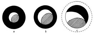
The effect on the field of view of this small diagonal in actual observations is illustrated in Fig. 49, where the fully illuminated part of the field, occupied in a and b by the picture of the moon’s disk, is shown as it would appear through eyepieces of 11/2″, 1″, and 14.” focal lengths, each having an apparent field of 36°. In the first instance, there is a gradual and probably unnoticeable falling off of illumination approaching the edge of the field, so that, for a single star at the extreme edge, the equivalent of slightly less than a 51/4-inch mirror is employed, which is hardly too bad. The losses in the second instance are of insignificant quantity, while in the third instance, the image of the moon (or fully illuminated field, outlined by the dotted circle) is too large to be fitted into the field of view of that eyepiece. If one is situated in a locality where the seeing is generally good, so that high magnifications can be consistently used, a still smaller diagonal might reasonably be chosen, but there appears to be little reason for making it larger.
Preliminary Preparations
The foregoing discussion may answer some of the questions most commonly asked concerning the optics of the telescope which could not be appropriately dealt with elsewhere. And now that the amateur is able to select the size of his diagonal with confidence in his judgment, the question of how to procure it remains to be answered. Indeed, it will be less troublesome and but little more expensive to purchase a diagonal than to make one. But in buying it, the amateur will be denied the fun that comes of making it, and besides, the precision of surface required is not always to be found in a commercial product. The choice of size is restricted, too, to the stock sizes of the manufacturer.
As we shall see, making the diagonal calls for ingenuity and forethought not required in mirror making, and has all the fascination of that activity. But it is neither laborious nor difficult, and once the preparatory operations are concluded, the diagonal itself can be made in a relatively short time. One should be fussy about these preliminary operations, as the departure from flatness must be kept to a very small tolerance.
Some additional equipment is required for making the diagonal, although much of the material gathered for making the mirror will be used. The diagonal will be made of plate glass, which ordinarily comes ¼thick, but the use of plate glass 3/8″ thick is recommended because it offers more resistance to flexure. When cemented to another piece during processing, thin glass may be strained or “sprung” through shrinkage of the cementing agent, particularly if the adjacent surfaces are not mates. As a consequence, after the figured diagonal is freed, the stresses that have been set up in it are relieved, and on return to a normal state the surface is no longer flat.
This effect is readily seen in testing two pieces of glass by the interference method described below. Pressing with the fingers around the edges causes the band pattern to deform and to assume a different shape while the pressure is maintained. When pressure is relaxed, the bands quickly assume a normal shape. Even relatively thick glass will deform under strain, and it will be recalled that in mirror polishing this made it • advisable that the weights used in lap pressing be equally distributed on the mirror at three points.
Several pieces of the selected plate glass should be available, or one rather large piece (one or two feet square) which will serve various purposes. A good straightedge; a glass cutter; more abrasives as required, cerium oxide or Barnesite preferred to rouge; onion sacking (already mentioned on page 70); a monochromatic light source; and a setup for testing described below, are among the items to be collected or prepared for making the diagonal. Also, it is important to have another thick piece of plate glass similar to the tool used for polishing the mirror; this tool will also be used.
How Flat a Diagonal?
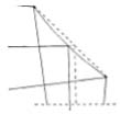
We have taken great pains to produce a curve of remarkable precision on our mirror. We should be equally concerned that nothing will interfere with the formation of a perfect image. In order to keep within the Rayleigh limit, each area of the diagonal that may be engaged in the formation of a point image may not depart from a true plane by more than 1/10 of a wave length of light. Such an area, elliptical in outline, is illustrated in Fig. 46. At a distance of 6½” inside the focus of a 6-inch f/8 mirror, the minor and major axes of this ellipse are 0.8″ and 1.12″, respectively; tnereiore a diagonal of double these dimensions would have to be flat to within 1/5 of a wave, measured along its major axis. The order of surface precision will, of course, depend on the dimensions of the ellipse shown in Fig. 46, which may vary according to the focal ratio of the mirror and the location of the secondary mirror in the cone. The surfaces of a prism must be flat to a similar degree.
Through examination of Fig. 50, it can be seen that if the diagonal is one wave length convex, the axial ray, aside from any other disturbances to which it may be subject, will be advanced from its proper position by 1.4 wave lengths. Hence, there is need for paying particular attention to the figure of the diagonal. Untested plate glass should never be used. Among several pieces of plate glass, each about 2″ square, seldom will one be found that is flat to better than 0.00004″. In general, the surfaces of such pieces also have different degrees of curvature on different diameters; in other words, they are astigmatic.
