Everyone is more-or-less familiar with the surveyor’s transit, in which two axes at right angles to each other enable the telescope to be aimed at any point in the celestial dome. Its motions are one in azimuth, about the perpendicular axis, and one in altitude, about the horizontal axis. The names of these motions have been combined in the term altazimuth, which is used to describe this type of mounting. When the telescope is swung through 360° in azimuth, the field of view traverses an orbit about the zenith, whereas the stars, in their daily or diurnal motion, describe orbits around the celestial pole.
However, if the instrument is tilted so that its perpendicular axis points to the celestial pole, instead of to the zenith, the former azimuth motion of the telescope will exactly follow the paths of the stars. This is then described as a motion in right ascension; its axis of rotation, parallel to the axis of the earth, is called the polar axis. The former altitude motion has now become one in declination, turning on the declination axis. This is now an equatorial mounting, taking its name from the great circle basic to this system of co-ordinates, the celestial equator.
When the telescope is mounted in this way, objects too faint to be seen with the eye can easily be found. Suppose, for example, we wish to observe the planet Neptune, assuming it to be above the horizon. We find its position (right ascension and declination) in the American Ephemeris. Then we swing the telescope on its declination axis so that it points the required number of degrees north or south of the celestial equator, and clamp it. Next we turn the telescope on its polar axis until the correct hour angle is read on the hour circle, and Neptune should be in the field of view. Of course, this procedure is possible only on an accurately adjusted telescope, equipped with setting circles, and if the sidereal time is known or computed for the time of observation. (See Chapter 14.)
There is one feature that must be emphasized in the design of a telescope mounting, and that is rigidity. Nothing is as abominable and useless as a telescope which trembles in the slightest breeze. Take a stick from a fire and whirl its glowing end before the eye in all sorts of gyrations — that is what the image of a star looks like in a weakly mounted telescope. Remember that any shake or vibration is amplified by the magnification being used, and what may appear to be a quite stable instrument may not prove so when you are trying to observe the Cassini division in Saturn’s ring with a 1/4″ eyepiece. Large size, smoothly operating bearings, well-fitting parts, and a sturdy support are required in an efficient mounting.

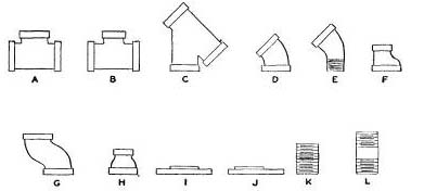
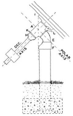
There is too great a latitude in ideas and design in telescope mounts for the subject to be entered into here. Our primary objective is to enable the amateur to mount his telescope cheaply and efficiently. What will be described is a conventional form of mounting known as the German type, utilizing pipe fittings, which are admirably adaptable to the purpose. A study of the problems of the construction will be of aid to those fortunate amateurs who are in a position to design and machine their own castings. The pipe fittings are obtainable in iron or brass at any steamfitters’ or plumbers’ supply house. Useful fittings are illustrated in Fig. 69. Shown in Fig. 70 is a fixed pipe mount in which the polar and declination axes turn on the threads of the short nipples L. The fittings are of 3″ pipe size, and can be identified from Fig. 69. The height of A above the ground should be such that the eyepiece is at a comfortable height when the tube is pointed to the zenith. For better bearing action, the threads of the polar and declination axes should be lapped in. To do this, paint the threads with a mixture of No. 400 carbo and cutting oil, and screw the tee, or flange, on and off repeatedly, grinding away until a few more threads become engaged. Then clean out all grit with a stiff brush and kerosene oil, screw the parts together again, and add lubricating oil. A much smoother turning action will be the result. No other machining is required on this simplified mounting. The counter-weight may be of iron, lead, or concrete.

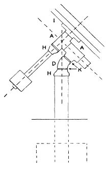
Another design is shown in Fig. 71, where a minimum of machining is called for. For this design, not less than 1 1/2″ pipe and fittings should be used, and preferably a size larger. The lengths of pipe which make up the polar and declination axes are turned perfectly round in the lathe, taking a minimum cut for the purpose. The internal threads of the tees are bored out only enough for the trued-up pipe to be fitted snugly into them. The faces of the tees ought also to be faced off, square to the boring.

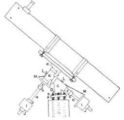
A third and perhaps the most satisfactory way of employing pipe fittings is shown in Fig. 72. In this design, 1″ pipe is used for the axes, with l½” fittings, and the intervening space is filled with babbitt metal. This gives a very smooth, rigid bearing, and it is possible in the construction to align the axes perpendicular to each other with good precision.
For the permanent mount, where weight is not a factor, 1 3/8″ solid bar stock is preferred to pipe, which must be machined perfectly round in the lathe. Bar stock is ground truly round, and it is only necessary to have the local plumber cut the pipe thread on it. Be sure in so doing that the vise jaws do not grip that part of the shafting that is to be encased in babbitt, as the resultant dents will cause trouble. Machined collars to fit the 13/8″ shafting can be purchased at the hardware store.
TableI. Specifications of Parts for Mounting
|
Fixed mount |
Portable “A” |
Portable “B” |
|
| A Heavy flange |
1½ |
Tripod head |
Tripod head |
| B Lock nuts |
½ |
None |
None |
| C Wye |
1½x1½x1½ |
Design of Fig 71 |
Design of Fig 73 |
|
1¼ elbow |
2 street elbow |
||
|
1¼ tee |
1½x1½x2 tee |
||
| D Close nipple |
1½ |
1¼ (?) |
2 (?) |
| E Reducing tee |
1½x1½x1 |
1¼x1¼x1 |
1¼x1¼x1¼ |
| F Length of pipe |
1⅜, 9 long |
1, 8 long |
1 & 1¼, 8 long |
| G Reducers |
1 x ¾ |
1 x ¾ |
1 x ¾ |
| H Extension pipe |
1 x 12 |
¾ x 12 |
¾ x 12 |
| I Counterweight |
Two |
Dec. axis only |
Dec. axis only |
| J Collars |
1 3/8 |
To order |
To order |
| K Heavy flange |
1 |
1 |
1 |
| L Clamping Screws |
3/8 |
3/8 |
3/8 |
| M Setting circles and pointers |
Polar and |
None |
None |

It ought not to be difficult to interest a local plumber sufficiently for you to borrow the paraphernalia requisite for the babbitting job — a fire pot on which to melt the babbitt, a solder pot, ladle, and torch. Or it is quite feasible to bring the assemblage to his shop and do the job there under his guidance. The entire operation of melting the babbitt and pouring a bearing may not take more than 15 minutes. About three to four pounds of babbitt will be needed for the bearings, but a surplus is needed for the pot, and may be used later in casting a counterweight. Use a good grade of babbitt; the difference in the cost of a few pounds is top small to risk deformation of a bearing that is almost pure lead. The babbitt must be heated to a point where a piece of cardboard will char if thrust into it.
Table II. Specifications of Standard Pipe Sizes
|
Size |
Outside diameter |
Inside diameter |
Nominal wall thickness |
No. threads per inch |
Depth of thread |
|
½ |
0.840 |
0.546 |
0.147 |
14 |
0.0571 |
|
3/4 |
1.050 |
0.742 |
0.154 |
14 |
0.0571 |
|
1 |
1.315 |
0.957 |
0.179 |
ny2 |
0.0696 |
|
1 ¼ |
1.660 |
1.278 |
0.191 |
ny2 |
0.0696 |
|
1 ½ |
1.900 |
1.500 |
0.200 |
ny2 |
0.0696 |
|
2 |
2.375 |
1.939 |
0.218 |
ny2 |
0.0696 |
|
1 ½ |
2.875 |
2.323 |
0.276 |
8 |
0.1 |
|
3 |
3.500 |
2.900 |
0.300 |
8 |
0.1 |
|
3 ½ |
4.000 |
3.364 |
0.318 |
8 |
0.1 |
|
4 |
4.500 |
3.826 |
0.337 |
8 |
0.1 |
The Babbitted Bearings
First, drill three holes radially near each end of the tee and wye (see Fig. 80) for No. 6-32 screws which will be used to center and support the shafting in the fittings while the babbitt is poured. The ends of these screws should be smoothed with a file so that they will not mar the surface of the shafting. Holes for the 3/8″ clamping screws (L, Fig. 72) should be drilled and tapped into the tee and wye, and the screws, coated with lampblack and oil, inserted prior to babbitting and brought up just to contact the shaft. The ends of these screws should first be filed quite flat. Two or three V cuts should also have been made across the internal threads of each of the fittings, the purpose being to provide grooves that will act as anchorage for the babbitt bearing.
Make up the polar axis tight in tee E. It will have to be removed later, so in order that it may again be returned to the same exact position, drill a hole through the branch opening of the tee into the shafting. In the final assembly, a pin or screw should be inserted in this hole. Slip the collar into place, snug against the tee. Now smear the polar axis and the collar with a mixture of thin lubricating oil and lampblack, to prevent the babbitt sticking to the metal.
Place the polar axis in the wye fitting, with its collar bearing against the upper face of the wye, and carefully center it with the set screws. To prevent the molten babbitt from running out, fit an asbestos paper or thin sheet-metal collar over the other end and seal up any gaps with putty. One or two pinhole perforations in the collar will allow the escape of air. Brace the assemblage so that it cannot roll during the pouring operation (see Fig. 81).
A poor bearing is apt to result if the babbitt is poured into cold metal, so while the babbitt is melting a torch should be used to preheat both casting and shaft. In heating the shaft, apply the flame to its protruding ends, else the oil film may be burned away, and there is then danger of the babbitt sticking to the metal. It is not necessary to bring the parts up to the temperature of the molten babbitt, which melts at from 500° to 600° F.; about 200° to 250° will suffice.
Make a trough of the asbestos paper or thin sheet metal, support it in the branch opening of the wye so that the babbitt, when poured, will not land directly on the shafting (see Fig. 81). Quickly pour in the molten babbitt until the shafting is well covered. When it has cooled, remove the centering and clamping screws and withdraw the shafting. A greater amount of expansion may have taken place in the casting than in the shafting and, upon cooling, the bearing may be extremely tight. If the shaft cannot be twisted free in the vise, hold a block of wood against its end and drive it through with a hammer. If it is still tight after being cleaned out, smear a mixture of cutting oil and rotten stone in the bearing, then push the shafting back in and work it around. This operation is known as lapping, and if it is not overdone a perfectly smooth turning action will result.
Now make up the declination axis tight in the heavy flange K, and slip one collar over it, up against the flange. Smear shaft and collar with the lampblack and oil, then approximately center it in tee E, and fix the second collar in position against the tee face. Some means of adjusting the two axes perpendicular to each other must now be found. The success of the final adjustments is dependent on the accuracy of this setting, so take plenty of time with it as it cannot be corrected after the babbitt has been poured, except by melting out the bearing. In order to adjust correctly the position of the declination axis, the polar axis must be temporarily screwed into the branch of the tee E, and the shaft then inserted in its bearing, already made. Rig up a makeshift pointer on the wye, contacting the declination axis at some point; then rotate the polar axis. through 180° and see if the pointer again contacts the declination axis. By repeated trials, and adjustment of the supporting screws in the tee, a very accurate setting can be arrived at.
Carefully, now, so as not to disturb the setting of the declination axis, unscrew the polar axis from the tee. Support the declination assembly as in Fig. 81, and babbitt. Be very careful in pouring not to bring the level of the molten metal up too high in the branch opening, or it might not be possible to screw the polar axis all the way back in.
When cool, remove the shaft from the bearing, and use gasoline to flush out the lampblack, burned oil, and other foreign matter. If the bearing is tight, lap it in as already described. A bearing scraper is a useful tool for dressing up rough parts. Finally, cut two washers of leather or other friction material and insert them ahead of the clamping screws, to cushion the thrust of the latter against the shafting.
Screw the polar axis back into the tee, and pin it securely in its original position; then smear clean lubricating oil on both axes, return them into their bearings, and the assembly is completed.
Further Suggestions
The amateur who has access to a lathe will, no doubt, contrive to machine the faces of the tee and wye, and so effect smoother performance. With careful planning of the whole operation, they can be made square with the axes. Added refinements, which are left to the discretion of the worker, are a worm-and-gear slow motion on the polar axis, and either a rack- and-pinion or a multiple-thread focusing arrangement on the eyepiece adapter tube. Note the provision for making latitude correction in Fig. 72. It will pay to take a little time in accurately setting the four bolts (only three are visible in the diagram) in the concrete pier, as adjustment will be greatly simplified if they are exactly oriented. A method of locating true north will be found in Chapter 18.