Nearly every optical principle as applied to a telescope requires consideration of the function of the eyepiece when the instrument is used visually. Most first telescopes are built for visual observing, so a knowledge of eyepieces is essential if the best possible results are to be obtained from the instrument as a whole. As will be seen in this chapter, there are good and poor eyepieces, and some good ones are not applicable to every type and size of telescope; be very sure, therefore, to equip your instrument with suitable eyepieces of good quality.
Magnification
In general, magnification consists of increasing the visual angular size of an object, which increase can be accomplished by reducing the distance between the eye and the object, either actually or apparently. In Fig. 66a, the distant object D subtends an angular size, a, at the eye. When its distance is reduced by half, as at D’, thereby doubling its angular size at the eye, the object appears twice as large (linearly) as before. And so, by means of further angular enlargement, an increasing amount of resolvable detail in the object is made visible.
But there is a physiological limit to which the distance from eye to object can be reduced. For a normal eye, 10″ is accepted as being the distance of most distinct vision; any lesser distance imposes an undue strain on the eye muscles. In Fig. 66b, an object, 0, removed about 10″ from the eye, subtends there the angle a. But, the better to define small detail, it is desired to bring the object to within an inch of the eye, at which relative distance its angular size will be increased up to 10 times (for small angles). The eye, however, although strained to the utmost, cannot accommodate for so small a distance, and the object appears blurred.
Therefore, to relieve the strain, a convex lens is introduced (Fig. 66c) to produce a virtual image of the object about 10″ in front of the eye, where the image can be examined in comfort. To meet these conditions, the lens in this case must have a focal length of 1″; the image 0’ will then be, apparently, 10 times the size of the object 0, or as the ratio of angle a’ to a. It follows, therefore, that the magnifying power of any single lens or combination of lenses used as a simple microscope is given by: M = 10/f, where f, in inches, is the focal length of the lens, or the equivalent focal length of a set of lenses.
|
|

In the case of a very distant object, the aid of a more complex optical system — a telescope — must be obtained. Here a lens or mirror of comparatively long focal length is made to produce a real image of the object at its focus, and the image is then magnified by a second lens (eyepiece) as was the object in Fig. 66c. These are the simple optics of the telescope.
In Fig. 66d, an image of a distant object is formed at I by the objective lens 0. The angular size of the distant object at O (or at the eye, since the object distance is very great) is equal to angle a, which is also the angular size of the image I. This image is mag- nified by means of an eyepiece, e, to the apparent angular size a’. It is evident that the linear size of the image depends on the focal length of the objective, and also that the focal length of the eye-piece will determine the size of the angle a’. Thus, the magnifying power of a telescope is given by:
M = F/f,
where F is the focal length of the objective, and f is the focal length of the eyepiece.
Although discussions of magnifying power found elsewhere may differ in some respects from the above, the equation last given is the definition of magnifying power which concerns the telescope when used for astronomical purposes.
Field of View
The real (angular) field of view, represented by angle a, Fig. 66d, is measured by that total portion of the image “plane” formed by the objective which can be accepted by the eyepiece. When this field is magnified to the apparent size of angle a’, it becomes the apparent (angular) field of view. Evidently, then,
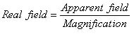
It follows, therefore, that as the magnification is increased the field of view becomes smaller. This effect is aptly illustrated in Fig. 49.

Exit Pupil and Eye Relief
In Fig. 67, a cylinder of essentially parallel rays from a star is collected by the objective and converged to a point intersection at the focus, which is also the focus of the eyepiece. Thence the rays diverge to the eyepiece and from this they again emerge parallel, but condensed into a smaller cylinder. The size of this cylinder is determined by the diameter of the objective, and also depends on the focal lengths of the eyepiece and objective. The diameter of the cylinder leaving the eyepiece is also the diameter of the exit pupil.
The location of the exit pupil, which is in reality an image of the objective and is called the Ramsden disk, will be a short distance back of the eye lens, at the place where the principal ray1 again intersects the axis after refraction by the eyepiece (see Fig. 65). As all the rays that pass through the objective to make up the image also pass through the Ramsden disk, it is essential that the lens of the eye itself be placed in that plane for most effective viewing. It is desirable to have as large an eye distance (usually called eye relief) as possible, especially with high powers, else one’s eyelashes will be rubbing against the eyepiece. In this respect, a single-lens eye-piece gives greater eye relief than the usual two-lens kind. And because this distance is never very great, spectacle-wearers should remove their glasses while observing and make compensation by refocusing the eyepiece; otherwise the field of view may be greatly curtailed.
The diameters of the exit pupil and of the objective have the same relative proportions as the focal lengths of the eyepiece and the objective, so the magnification of a telescope may also be expressed as:
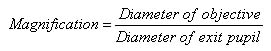 |
By focusing the telescope on a very remote object and then withdrawing the eye to a distance of about a foot, the exit pupil will be seen apparently suspended in air just back of the eyepiece. It is more conspicuous if, after focusing, the telescope is pointed at the daytime sky. The diameter of the exit pupil can be quite exactly measured by means of calipers or a fine scale held in the plane of the Ramsden disk. A magnifier will aid in obtaining an exact measurement. The above formula will give the magnification of the telescope, and by the F/f formula an exact determination of the focal length of the eyepiece can be made.
It is evident that as the magnification is reduced, the exit pupil increases in size. But it should not be permitted to exceed the diameter of the pupillary opening of the eye, for reasons about to be explained. In darkness, the average pupil diameter is between 71/2and 8 millimeters, as determined by several authorities. However, in the presence of illumination from a bright star field, some contraction will take place, and a diameter of 7 mm. has been generally accepted as a standard, although it is true that some eyes are able to receive an exit pupil of 7½ mm. or more. Suppose, for example, an eyepiece of 3″ focal length were used with a 6-inch f/8 mirror, yielding a magnification of 16 and an exit pupil of 9½ mm. As only 7 mm. of this could enter the eye, and as the effective aperture of the mirror is equal to the magnification multiplied by the exit pupil diameter, it is apparent that only about 4½” of the mirror’s diameter will be employed. The outer zones are actually diaphragmed out by the iris of the eye. The net result, indicated by the dotted lines in Fig. 67, is a waste of aperture, accompanied by a loss of illumination.
The value of a 7-mm. exit pupil is that it provides the widest possible field of view commensurate with the proportions of the objective, and is desirable in certain kinds of observations, such as comet seeking. A practical example is the 7 x 50 binocular which is standard equipment in the U. S. Navy. This is the so-called night glass, most useful in the deepening twilight. It is a 7-power glass, with 50-mm. (2-inch) objectives. The exit pupil is therefore 7 mm. in diameter, quite filling the expanding pupillary opening in the dim light.
When taking the first look through his telescope upon completing the alignment, an amateur may have been troubled by the conspicuous shadow of the obstructing diagonal, especially if a low-power eyepiece were used at the time. Of course, he was pleased, and perhaps mystified, to find that the objectionable shadow was not apparent at night. This is because the image of the diagonal, projected on the Ramsden disk, may be fully half as large as the pupillary opening of the eye in broad daylight, whereas it is inconspicuously small by comparison with the greatly expanded pupil at night. Therefore, in daytime or terrestrial observations, high-power eyepieces should be used if this disturbing shadow is to be avoided. Low magnifications can be successfully employed with use of the diaphragm shown in Fig. 87, whereby the central obstruction is eliminated. The loss of aperture in that case is not a matter of great concern, as there is usually an abundance of illumination in the daytime.
Theoretically, the smallest exit pupil which ought to be used is one that will exhaust the full resolving power of the mirror. This occurs when the magnification is high enough to reveal all the detail in an object, or, in other words, when the diffraction disk becomes visible. This condition is reached with a magnification of about 13 per inch of aperture, when the exit pupil becomes about 2 mm. in diameter. Practically, however, as stated in Chapter 18, in the section Resolving Power, it will frequently be necessary to resort to considerably higher magnifications.
Eyepieces
The apparent field of a single convex lens used as an eyepiece is considerably smaller than assumed in Fig. 66d. It can be seen in that diagram that unless the angle a is small, the field rays from the edges of the objective, after passing through the edges of the image plane, will miss that eyepiece altogether. And, because of inherent aberrations, the sharply defined portion of the visible field will be further reduced, extending not more than 5° on either side of the axis.
It was chiefly to overcome this defect of the single lens that the compound or two-lens ocular was devised. For example, by placing a convex field lens in the vicinity of I (Fig. 66), the divergent rays referred to above can be collected and converged and made to enter the eye lens; thus a considerably larger field of view can be encompassed. This is shown to advantage in Fig. 65, the Ramsden eyepiece there having an apparent field of 36°. Placed so close to the focal plane, the field lens contributes but little to the magnification, most of which is accomplished by the eye lens, but by a suitable choice of the focal lengths and separation of the components, aberrations can be materially reduced. The equivalent focal length (e. f. I.) of a combination of two lenses when thus used is equal to that of a single lens that will yield the same magnification, and is:
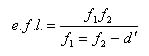
where d is the separation of the lenses.
The linear size of the real field of view can then be taken as approximately the same as the diameter of the field lens of the eyepiece. For an equivalent focal length of 1″, the clear aperture of the field lens may be about 0.7″; a field of this width at the 48″ focus of a mirror will have an angular size of about 50 minutes of arc. As the magnification realized in this instance will be 48 (F/f), the field will be enlarged to an apparent diameter of 40°; a field of this size is frequently attained in a two-lens eyepiece.
Broadly speaking, astronomical eyepieces or oculars can be classified into two types, negative and positive. In the negative type the image is formed between the lenses, or within them, thereby precluding the use of this eyepiece as a simple magnifier. The negative type is represented chiefly by the eyepiece devised by Huygens. Most prominent of the positive types are the oculars of Ramsden and Kellner. All these eyepieces, for astronomical use, should be mounted in standard-sized tubing of l¼ outside diameter. As to focal lengths, a wide choice is available to the amateur, ranging from about 1½” down to 14″ and less. The field lens of the lowest power will be about 1″ in diameter, as compared to 1/8″ or less for the highest powers. Probably the most frequently used eyepiece is one of 1″ focal length, and good choices to supplement it are focal lengths of 2/3″ and 1/3″, although l/2″ and 1/4″ are more popular. Where a telescope does not have a finder, a low-power eyepiece of about 1½” focal length is a convenient aid in locating objects.
The Huygenian eyepiece (Fig. 68, top) is composed of two plano-convex lenses, of unequal focal lengths, in which the convex surfaces face away from the eye. The field lens is placed inside the focus of the mirror, resulting in a slightly smaller image being formed a little closer to the mirror, the image then being magnified by the eyepiece alone. A diaphragm, excluding all but the useful rays, is placed in the focal plane of the eye lens, about midway between it and the field lens. The well-defined apparent field of view is nearly 40° wide. Because of spherical aberration, the Huygenian does not perform as well as the Ramsden or Kellner types on moderate- or low-ratio telescopes, but when used at f/10 and above it leaves little to be desired.
In the usual design of the Huygenian, the focal lengths of the field and eye lenses are in a ratio of 3 to 1, with a separation of half the sum of the focal lengths. Thus, in an eyepiece of 1″ equivalent focal length, the focal lengths of the field and eye lenses are 2″ and 2/3″ respectively. Their separation is 11/3″, measured, approximately, between the convex surfaces. In the Ramsden, or positive ocular (Fig. 68, center), likewise consisting of two plano-convex lenses, the convex surfaces face each other. Well corrected for spherical aberration, this eyepiece performs effectively on all sizes of telescopes, and is preferred to the Huygenian for use on Newtonian reflectors. In its most corrected form, the lenses are of equal focal lengths, and separated by a distance equal to their mutual focal length. But with the lenses so spaced, a scratch or any dust on the field lens is brought into sharp focus and magnified by the eye lens. Nor can a reticle be used with such a combination. Accordingly, it has been found expedient to move the field lens out of focus by bringing the lenses closer together, at the cost of introducing a tolerable amount of color into the outer parts of the field. Best separations vary from two thirds to three quarters of the focal length of either lens. The focal plane lies a short distance in front of the field lens, and the eye relief, somewhat better than in Huygens’ eyepiece, is thereby further improved.

Specifications for the generally approved Ramsden designs, for equivalent focal lengths of 1″, are as follows: (1) focal length of each lens, 1 1/3″, separation 0.89″; (2) focal length of each lens, 1 1/4″, separation 0.93″. The lesser spacing affords greater eye relief, and so is preferred for high powers. The good, sharp field of either arrangement is about 30° in extent, but fields from 35° to 40° are usually provided.
A modification of the Ramsden ocular, in which the eye lens is formed of an achromatic combination of crown and flint glass, is called the Kellner (Fig. 68, bottom). This eyepiece gives a flat, almost colorless field about 50° in diameter, about as large a field as can ordinarily be used. It is highly recommended in low powers, where its wide field can be used to advantage in variable star work, comet seeking, and so forth.
Specifications, for an equivalent focal length of 1″, are: focal length of field lens, 1¾”; focal length of eye lens, 1 1/3″; separation ¾”. Troublesome “ghost” images are sometimes present with both the Kellner and Ramsden oculars, arising from reflections originating at the convex surface of the field lens and coming to a focus close to the focal plane of the eye lens. These can be materially subdued by coating both field-lens surfaces with an anti-reflection fluoride, at the same time improving the image brightness. Indeed, so marked is the improvement in the performance of fluoridecoated optical elements that uncoated lenses are as outmoded as speculum mirrors.
In a general way, this summarizes the characteristics of the more commonly used astronomical eyepieces. Slight variations from the specifications given are frequently resorted to in order to reduce one or another of the several aberrations. But the amateur must be wary of eyepieces not known to come from a reliable manufacturer of optical goods. A good eyepiece is not cheap — it may cost six or seven dollars or more. Occasionally, an unscrupulous dealer will select from stock an ill-matched pair of lenses that will yield an image, mount them in a cell, and offer them for sale. Such eyepieces are usable, but image formation may suffer considerably, and no reliance can be placed on the assigned focal length.
Aberrations of the Eyepiece
Only the most prominent of these will be briefly discussed: chromatic aberration, distortion, curvature of the field, and spherical aberration. Chromatic aberration is of two kinds, longitudinal (illustrated in Fig. 4), and lateral. The latter is caused by unequal magnification of the different colors, and is more properly known as chromatic difference of magnification. The physical effects of the above aberrations (except spherical) can be readily observed by the possessor of a telescope when a simple lens of about 1″ focal length is employed for the eyepiece. If one of the lenses is removed from a compound ocular, such an experimental eyepiece is had already mounted. (For these experiments, the telescope can consist simply of a small achromatic lens of not less than about 6″focal length, taped to one end of a short mailing tube.)
Longitudinal chromatic aberration, uniform in amount throughout the field, is revealed when observing a twig or telephone wire against the bright sky. If you push the eyepiece first inside and then outside of focus, the object will be seen in different colors. Both positive types of eyepiece (Kellner and Ramsden) have better correction for this fault than does the Huygens.
The balance of the experiments may be performed by observations on the straight-edged roof top of a distant building silhouetted against a bright sky.
Chromatic difference of magnification is shown by the increasing amount of color that is seen bordering the roof line as it approaches the edge of the field. Axial images are unaffected, but the error increases in intensity in proportion to the distance from the center of the field. The Huygens eyepiece is practically free of this defect, while there may be a troublesome amount in the outer parts of the field of the Ramsden. Some color is also present in the Kellner eyepiece.
Distortion shows up on displacing the roof line toward the edge of the field, when its straight edge is seen to become curved, convex toward the center of the field. This is due to unequal magnification of different parts of the image, the aberration increasing as the cube of the distance from the axis. Intolerable in certain terrestrially used telescopes, this aberration is an innocuous one as far as general astronomical observation is concerned. All three compound eyepiece types are substantially free of this error, although more complete correction is found in the Kellner and Ramsden.
Curvature of the field, increasing in amount with the square of the distance from the axis, becomes apparent when the telescope is shifted so that the roof line again divides the field in half; if the center is in sharp focus, curvature of the field makes it necessary to push the eyepiece inward in order to bring the edge into equally sharp focus. Only partially corrected in the Huygens eyepiece, the defect is almost completely removed from the Kellner and Ramsden. Spherical aberration (illustrated in Fig. 5) is an insidious error, difficult to detect in a single lens because of the small amount of the aberration present. Where an excessive quantity of spherical aberration is produced, the diffraction pattern (see Chapter 18) becomes blurred, and contrast suffers. The best obtainable image may remain apparently unchanged in quality throughout a small but perceptible movement of the eyepiece. In any given eyepiece, the fault varies as the square of the angular aperture of the objective with which the eyepiece is employed. (Angular aperture is the angle, at the focus, subtended by the objective lens or mirror — see Fig. 67.) For this reason the Huygens, uncorrected for the defect, does not perform well on telescopes of moderate focal ratio; in fact, at f/7 and lesser ratios, it is entirely unsatisfactory. Both the Ramsden and Kellner eyepieces are relatively free of spherical aberration, with the Ramsden surpassing the Kellner in this regard.
Assembling Eyepiece Components
The making of small lenses is a craft that will not be discussed here, as there is already considerable literature on the subject, available to those who would like to experiment in that direction. It might be mentioned, however, that a spindle and lathe are essential for eyepiece manufacture. Eyepiece making is a fascinating hobby. If one is talented in working to small dimensions, he can, with a little practice and the selection of good glass, succeed in producing as good eyepieces as can be obtained anywhere.
An excellent eyepiece can be assembled from a suitable choice of plano-convex lenses. The focal length of a plano-convex lens is equal to twice the radius of curvature of the convex surface, but as this will very likely be unknown, the focal length can be found by measuring the distance from the lens to the bright image of the sun which is formed by the lens. Or stand it between an illuminated pinhole perforation and a screen. When arranged so that a sharply focused image of the pinhole falls on the screen with the lens exactly midway, the focal length is one half either distance. Or, at any distance, the formula for conjugate foci can he applied:

where F is the focal length, Do and Di the distances to pinhole and image. Measurements are made from the convex surfaces. The formula for the equivalent focal length of two lenses has already been given. An excellent adjunct to experimentation with small lenses is plasticine or sculptors’ modeling clay. A wad of such material stuck on a board will hold the lenses securely fixed, and they can be manipulated at will.
