The materials and equipment which are needed to produce the mirror are:
A 6-inch pyrex mirror blank, from Corning Glass Co., Corning, N. Y. The sides of a pyrex blank are tapered, giving to one surface a slightly larger diameter than the other. The larger surface is the one that is to be ground to curve for the mirror.
A 6-inch plate-glass disk, of a thickness at least 1/8the diameter, from any plate-glass manufacturer. This is to serve as the tool.
Abrasives (in the order in which they are to be used): carborundum, No. 80, 8 ounces; No. 120, 3 ounces; No. 220 and No. 400, 1 ounce each; alundum (fused aluminum oxide), No. 600 (or No. 2 garnet powder), ½ ounce; emery, No. 305 (or No. 8 garnet powder), ½ ounce.
Carborundum is a synthetic abrasive. The grains are separated into numbered sizes by passing them through a mesh of a. corresponding number of strands per inch. It is considerably harder than emery, and in the coarse-grain size is about four or five times as efficient.
Emery, a variety of corundum (native aluminum oxide), is a mineral deposit. It .is first broken up into powder form, and then graded by elutriation; that is, by repeatedly stirring in water and pouring or siphoning off the liquid, finer and finer settlings are obtained.
Garnet is also a mineral, and is treated in the same manner as emery. It is a cheaper product, but just as effective as an abrasive.
Polishing agents: choice of fine optical rouge (red), cerium oxide, or Barnesite, 4 ounces.
Red rouge (Fe2O3) is a product of iron oxide. This compound and to a lesser extent black rouge, another iron oxide, have for years been the only agents used in the polishing and figuring of fine optical surfaces.
Cerium, a metallic element, the oxide of which was discovered in 1803, was named for the asteroid Ceres, which had been found two years earlier. The oxide (CeO2) is pale pink in color, has none of the messiness of rouge, and polishes two to three times as fast; many optical workers have recently used it in place of rouge. Some cerium oxide samples, on being sifted between the fingers, seem to contain rather coarse particles, but evidently in slow hand polishing, as on mirrors, these lumps disintegrate without doing any harm, as extensive trials have failed to produce a single scratch. In machine polishing, which is entirely different, cerium oxide does sometimes scratch, and the finer Barnesite is used for the finish polishing.
Barnesite (trade name), brown in color, is compounded of the oxides of several of the rare earths. It is finer than cerium, is perhaps as rapid in its action, and probably yields the most superior polish of all three products.
For a further discussion of polishing agents, refer to the section, Theory of Polishing, in Chapter 6.
Obviously, in purchasing grinding and polishing agents directly from manufacturers, somewhat larger quantities than those given here will have to be ordered. It may be more economical to obtain the small quantities needed from a local optical shop, if it will sell them, but bring along your own containers as a precaution against mixing the grades. The small jars with screw covers which druggists use for ointments are excellent. Always dispose of any grade which should chance to become contaminated with a coarser one.
For the lap, about one pound of pitch should be obtained, as well as half a pound of rosin, and about two ounces of beeswax. Most optical pitch is a refined pine-tar product, a viscous fluid which, when cold, assumes a solid shape but flows under pressure. It usually has to be tempered with rosin or turpentine.
Rosin, beeswax, and sometimes a satisfactory grade of pitch can be obtained from a paint or hardware store. Pitch of doubtful purity, after being melted, should be strained through cheesecloth.
Sources of supply for these materials are: carborundum, Carborundum Co., Niagara Falls, N. Y.; alundum, Norton Co., Worcester, Mass.; emery and rouge, American Optical Co., Southbridge, Mass.; Bausch & Lomb Optical Co., Rochester, N. Y., also supplies a fine grade of rouge. All of the abrasives and polishing agents listed, as well as pitch and other accessory materials, can also be obtained from the Universal Shellac and Supply Co., 401 Broadway, New York 13, N. Y. Kits that should contain suitable quantities of the necessary materials can be bought from some supply houses.
Miscellaneous items: Also needed are a water pail; a water bottle or shaker, such as a cruet (or a tin can with a perforated cover); a coarse and a fine carborundum stone; turpentine; paraffin; a small paint brush from the 5 & 10 for applying the rouge; and a magnifying lens about 1″ to 1½” m focal length. Also a small pot; empty cans for melting the pitch, beeswax, and paraffin; and an electric hot plate or gas burner.
To be made or improvised are: a template; a channeling tool; grinding stand or barrel; testing rack for the mirror; Foucault testing device; and stands to support the last two items. See page 41 for a list of mirror making materials and equipment.
|
|
The Template
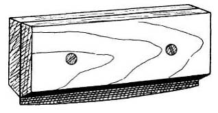
This is used to gauge the curve on the mirror during coarse grinding. It should be given a radius of curvature of 98″, although the completed mirror should have a radius of 96″. The template is best made from thin sheet metal, 0.006″ to 0.010″ in thickness, and about 8″ square. To cut the curve, first nail the sheet metal to the floor. Drill two holes 98″ apart in the ends of a long stick, and nail one end to the floor so that the other end is free to swing across the metal sheet. Insert the point of a strong knife blade into the hole at the free end, and cut through the metal in a single sweep. With the magnifier, examine the convex edge for burrs, and carefully file them off. The template should be protected from bending by securing it between two thin boards, with its edge protruding about l/4″. Since a difference of 0.001″ in the sagitta of the mirror means a difference of about 1″ in focal length, great care must be exercised in testing with the template; watch carefully for any streaks of light that might show up between its edge and the surface of the mirror. See Fig. 15 for a diagram of the finished template.
The sagitta is the depth of the curve at the center, as measured between the mirror’s surface and a straightedge laid across any diameter. It can be found with sufficient exactness from the value of r2/2R, where r is the radius of the mirror, and R its radius of curvature. For our 6-inch f/8 mirror, it is 9/192 or 0.047″.
Channeling Tool

This is used in forming the squares in the pitch lap (Fig. 16). It should be at least 8″ long, with a cross section like that shown in Fig. 16. A length of channel iron of these dimensions, or slightly smaller, will do, or the channeling tool may be made out of wood. It will not be needed if a molded lap is used. (See Chapter 5.)
Grinding Stand
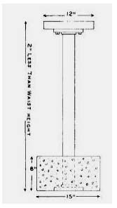
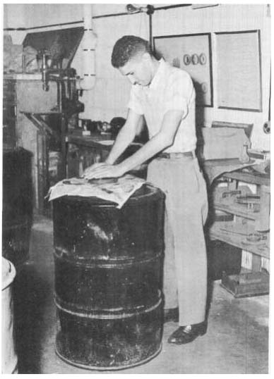
Considerable friction is encountered in polishing, so the grinding stand must be rigid and heavy. A weighted barrel with a reinforced top will do nicely. A stand like that shown in Fig. 17 is sturdy, cheap, and easily put together. A 36″ to 40″ length of 2½” or 3″ pipe, screwed into a heavy flange, is set in a block of concrete. Another heavy flange is fastened to the heavy wooden top with small lag screws, and screwed tightly to the upper end of the pipe. A small cabinet in which to store the abrasives may be built in around the pipe.
Mirror Testing Rack
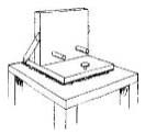
Fig. 18 shows a conventional form. The mirror is supported on two dowel sticks spaced about 4″ apart. The rack rests on two pegs at the back, and on the adjusting screw in front, which is used to tilt the mirror up or down.
|
|
|
Testing Stands
Measurements will have to be made in hundredths of an inch, so the testing stands must be sturdy, and rest solidly on the floor. Any vibrations which result from passing trains or other traffic may sadly disrupt testing, so a concrete floor is preferred. If stands have to be built, they should be designed so that testing can be conducted in a comfortable sitting posture, and so that the center of the mirror, pinhole, and knife-edge are all at about the same level.
Foucault Testing Device
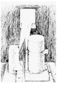
The requisites are a light source contained in an opaque shield in which there is a pinhole perforation, a knife-edge, and a scale for making measurements. Fig. 19 illustrates a practical testing device. The baseboard is a flat well-seasoned board, such as ¾”-thick plywood, about 6″ x 9″ in size. The guide cleat, a straight-edged stick 1″ wide and 6″ long, is attached to the baseboard about 2½” in from one edge. Fastened to this cleat in a suitable position is a strip of metal or plastic material on which has been scribed the scale shown in Fisr. 20. The scale should be made under a reading glass for best accuracy. The horizontal lines are spaced 0.1″ apart, and the vertical lines 0.2″ apart. The diagonal lines divide the verticals into fiftieths of an inch, and interpolation can be made for readings to hundredths of an inch.
The knife-edge, of rectangular shape, and with a perfectly smooth edge, is cut from a thin piece of sheet metal, and tacked to a block of wood about 1½” x 3″ x 3″ in size. If the lower part of the piece of sheet metal is cut and bent at right angles, as can be seen in Fig. 19, and attached to the block so that this edge just skims the surface of the scale in Fig. 20, it will also serve as the indicator. This indicator edge must be exactly parallel to the horizontal divisions of the scale when the block bears against the cleat. For the light source, an ordinary 50-walt frosted lamp and socket are fastened to a 4″ x 4″ block of wood. A section of small stovepipe, or a tall can with both ends cut away, is set over the lamp. A “window” or hole about 1/8in diameter is drilled into the side of the can at a height opposite the bright spot of the lamp. A band of thin sheet metal, containing two or three pinholes of different sizes, is clamped around the can so that it can be slipped down over the window. Two pin-holes, placed one above the other and about 14″ apart, will suffice.

To make these, thin an area of the metal band with a file and emery paper until it is only one or two thousandths of an inch thick; lay it on a piece of glass, and, twirling a needle between the finger tips, pierce the first hole. Stop when the needle just breaks through, and examine the hole against a light with the magnifier to see that it is perfectly round. Any burrs should be removed with fine emery paper. For a finer hole, sharpen the needle on a fine stone, twirling and drawing it out at the same time under the finger tip, until it appears perfectly sharp under the magnifier. Pierce the hole as before, using less pressure. Holes about 0.005″ to 0.010″ in diameter are probably most satisfactory, but the size will depend on the amount of illumination used, which can, of course, be concentrated and intensified on the pinhole through the introduction of a condensing lens. Too small a pinhole may not admit sufficient light; a large hole is lacking in sensitivity. Foucault used a pinhole 1/12 of a millimeter (about 1/300 of an inch) in diameter.
To avoid discomfort from the heat of the lamp, and to bring the pinhole and knife-edge into closer proximity, a small right-angle prism may be used. Instead of the window of the lamp-container facing the mirror, turn it 90° to the left, so that it faces the knife-edge, and mount the prism as in the picture, on a block of wood, directly in front of the window or pinhole opening. A small chipped prism can be picked up for a few cents from dealers in optical goods.
A great many rulinemenls arc often added in an effort to increase the efficiency of this device, including an arc-light source, condensing lenses, extremely small pinholes or an adjustable slit, and knife-edge motions controlled in two directions by micrometer screws. But the seemingly crude device described should enable the reader to produce a mirror capable of the finest possible definition. Of course, the accuracy of the scale and one’s ability to read it accurately determine its worth.
Nearly as simple to construct, and requiring no scale, is a small table, on which the knife-edge can be mounted, that rolls between guides on three ball bearings. A screw, which substitutes for the scale, controls the motion, with rubber bands or tension springs taking up the slack by an opposing pull. As the tension will have a tendency to lift the table from the ball bearings, the table should be weighted. Almost any thumbscrew will be suitable, or a piece of threaded rod into one end of which a pin is inserted at right angles, making a T-handle.
The number of turns and the number of threads per inch determine the extent of longitudinal motion. For example, consider a screw having 24 threads per inch, a standard number. This may be regarded as approximately 25 per inch, with a single revolution equal to about 0.04″, and a quarter revolution (easily estimated from the change in position of the T-handle), about 0.01″. Two and a quarter turns of a 24-thread screw will therefore yield an exact measurement of 0.094″, the full amount of correction called for on the 6-inch f/8 mirror (see Chapter 7 for an explanation of correction), probably with a greater degree of accuracy than could be obtained from the first device.
Theory of the Foucault Test
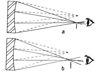
This method of testing a concave reflecting surface was devised by Jean Foucault, of pendulum fame. The impressive features of this test are its simplicity and extreme sensitivity. Foucault’s theory was that if an artificial star (illuminated pinhole) be placed at the center of curvature of a spherical mirror, then all of the rays from it that fall upon the surface of the mirror will be perpendicular thereto and, by the law of reflection, will be returned along the same paths, to form an image of the pinhole on the pinhole itself. Of course, the image could not be examined in this position, but if the pinhole were shifted to one side (we shift it to the right), the image would be shifted a corresponding distance to the other. Now if a knife-edge be cut into this image at right angles, all of the rays will be at once intercepted, and if the illuminated mirror were being viewed by the eye as shown in Fig. 21a, it would appear to darken instantly. But if the curve on the mirror deviates the slightest amount from a true spherical figure, then all of the rays will not intersect in that pinhole image. Instead, rays^ from those zones of different curvature will intersect in slightly separated points along the axis of the reflected cone of light. One such variation of surface curvature is shown in Fig. 21b. Here, the knife-edge could nowhere be placed so as to intercept all of the rays at once, and to the eye viewing the mirror, those parts from which rays had been intercepted would appear dark, while the other parts would still appear illuminated. By exploring along a small range of the axis of the cone with the knife-edge, and measuring the distance between the points of intersection of these radii, it is possible to tell what our curve is, almost to the millionth part of an inch.
|
|
Mirror Materials Check List
|
Item |
Quantity |
|
|
1. |
6-inch pyrex mirror blank |
1 |
|
2. |
6-inch plate-glass disk |
1 |
|
3. |
Abrasives: | |
| Carborundum # 80 |
8 oz. |
|
| #120 |
3 oz. |
|
| #220 |
1 oz. |
|
| #400 |
1 oz. |
|
| Alundum #600 or #2 garnet powder |
½ oz. |
|
| Emery #305 or #8 garnet powder |
½ °z- |
|
|
4. |
Polishing agent: | |
| Rouge, cerium oxide, or Barnesite | ||
|
5. |
For the lap: | |
| Pitch |
1 lb |
|
| Rosin |
½ lb |
|
| Beeswax |
2 oz. |
|
|
6. |
Miscellaneous items: | |
| Water pail |
1 |
|
| Water bottle or shaker |
1 |
|
| Carborundum stone (coarse & fine) |
1 ea. |
|
| Turpentine | ||
| Paraffin | ||
| Small paint brush |
1 |
|
| Magnifying lens (eyepiece) |
1 |
|
| Small pot |
1 |
|
| Empty cans |
3 |
|
| Hot plate or gas burner (kitchen stove will do) |
1 |
|
|
7. |
To make or improvise: | |
| Template |
1 |
|
| Channeling tool (or rubber mold) |
1 |
|
| Grinding stand or barrel |
1 |
|
| Foucault testing device |
1 |
|
| Testing rack |
1 |
|
| Stands for testing device and rack |
1 ea |
The various grades of abrasive listed opposite are by no means the only sizes that may be used. The transformation of the mirror’s surface from a coarsely pitted one to the satin-like finish requisite for quick and complete polishing can be made with any series of progressively smaller grain sizes. It is expensive and time consuming to encumber the operation with many different grades, and yet if too large a gap exists between the various sizes, an undue length of time will have to be spent with each one. Hand grinding of a pyrex mirror is perhaps most efficiently accomplished with not fewer than six judiciously chosen grades. Use of a larger number is not necessarily a greater assurance of success, however, as there have been many instances where, with as many as 12 different sized abrasives being used, coarse pits still remained, and the last few stages had to be repeated.
It is not absolutely essential that the plate-glass tool be of the thickness recommended on page 34, but the thickness should never be less than 1/12 the diameter. For unless the surfaces of both tool and barrel top match quite perfectly, such a thin tool might yield slightly under the pressure of grinding, or the weight of cold pressing when polishing, and it would be difficult to maintain a surface of revolution. In any upside-down grinding, a thin tool is sure to bend under the pressure, and a spherical surface under these conditions is almost an impossibility. In considering the matter of thickness, see Chapter 9 for further uses to which the tool may be put.
|
|
