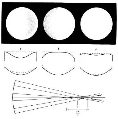
The center of curvature thus found is not that of the extreme edge zone, but of a zone of 2.8″ radius, or the mean radius of the zonal opening. A calculation will show that the center of curvature of the extreme edge zone, which is what is ultimately sought, lies about 0.01″ farther from the mirror. Consequently, when it is deemed that the shadow appearances in the edge openings conform to prescription, the knife-edge should be withdrawn from the mirror by that amount. A magnifying glass will be of assistance in making a precise setting. Now remove the mask and observe the over-all shadow appearance on the mirror. As the knife-edge is again cut in, the first shadow to appear will be seen 0.9″ inside the right-hand edge of the mirror (actually at the 70-per-cent zone). With further movement of the knife-edge, this shadow expands, moving somewhat slowly toward the right-hand edge, and more rapidly toward the center of the mirror. Finally, it reaches the mirror’s right edge and center together, and at the same moment a thin wisp of shadow appears on the left edge, the mirror then having the dish-like appearance shown in Fig. 39a. As you continue the knife-edge movement, the shadows at the left edge and the center approach and meet at the 70-per-cent zone on that side, and the whole mirror is darkened. These are the shadow appearances when the knife-edge is at the center of curvature of the edge zone, and unless they behave as described, the mirror does not have the paraboloidal shape. Note carefully the indicator reading on the scale.

|
Replace mask A; then slowly slide the knife-edge toward the mirror, stopping frequently to cut it into the cone of light, and observe the passage of the shadow on the centrally exposed portion of the mirror. At first, the shadow will definitely be seen to come in from the right, because the knife-edge is, relatively speaking, still well beyond the center of curvature of the central zone, but as this point is approached, the direction from which the shadow comes in becomes less apparent. When a position has been found where this exposed area is seen to darken all over, instantly and evenly, just as though it were a small spherical mirror, and no perceptible direction of shadow approach is apparent, the setting may be accepted as the center of curvature of that zone. Again note the scale reading shown by the indicator. The difference between this setting and the one found for the edge zone should equal the value of t2/R, or lie within the recommended tolerances.
We must acquaint ourselves with the over-all shadow appearances at all zonal settings, so after removing the mask, we again cut in the knife-edge. The shadow is seen to appear on the left-hand edge of the mirror, moving slowly at first, then with increasing rapidity until upon reaching the 50-per-cent zone (halfway from the center of the mirror to the edge), it suddenly sweeps across the central part of the mirror. The left-hand zones of the mirror are then dark, and the central part, bounded by the mirror’s 50-per-cent zone, appears flat and gray. In appearance, the mirror resembles a bowl turned bottom side up (Fig. 39b). Special attention should be paid to the upper and lower shadow boundaries as the shadow encroaches on the mirror. These should appear to terminate at the “poles” of the mirror, from which points the shadow seems to pivot. If there is any straightening or outward bending of the shadow, the indication is that the outer zones of the mirror are insufficiently corrected. This test becomes more delicate if the knife-edge is tried a small distance inside of focus.
It is entirely possible, as we shall see when we come to the parabolizing strokes, for the over-all correction to be right, and yet for the mirror not to have the paraboloidal shape. It is true that the difference cannot be great in the case of the 6-inch f/8; nevertheless the zonal aberration from a mirror of sufficiently irregular figure may be of a rather large order. Of course, at either of the above knife-edge settings, any irregularity in the progression of the curve would be instantly detected by the experienced worker through misbehavior of the shadows, but it might be asking too much of the tyro to expect him to match the veteran’s skill in observation and judgment. It is therefore necessary to test an intermediate zone of the mirror, the one most suited to the purpose being the 70-per-cent zone, and for this mask B is used.
The value of the mask for the.70-per-cent zone is questionable, but so many beginners feel that it is beneficial in enabling them better to grasp the fundamentals of the test that its use is suggested.
Now, as closely as possible, place the knife-edge exactly halfway between the above two settings, and cut it in. Faintly gray shadows should appear simultaneously in each zonal opening, there being no indication of the direction of approach. However, if overcorrection is present (or if the mirror has a lesser ratio than f/8), the shadows in each opening may be seen to come in from the left, but they must come in together. If a shadow appears in the left-hand opening first, the indication is that the central part of the mirror is overcorrected; if seen in the right-hand opening first, then there is a preponderance of correction in the edge zones. Here, too, diffraction from the edges of the zonal opening of the mask will have a disturbing effect on the worker in scanning for the shadows, but if these luminous outlines are not lookedat, their disturbing effect will be materially lessened.
Removing the mask, we once more cut in the knife-edge. The first shadow to be seen moves in on the left-hand edge of the mirror, immediately followed by a second one appearing in a spot midway between the center of the mirror and the right-hand edge, in other words at the 50-per-cent zone. As the knife-edge progresses across the pinhole image, the second shadow expands, spreading quickly to the right, and more slowly to the left; at the same time the first shadow is moving farther in on the mirror.
When the knife-edge has reached the axis of the reflected cone of light (the actual point of intersection of rays from the 70-per-cent zone), the second shadow should extend from the center of the mirror to the 70-per-cent zone on the right; the first shadow should have reached the 70-per-cent zone on the left. The mirror now should have the appearance shown in Fig. 39c. The crests of the convex curves marking the 70-per-cent zone should form the boundaries of the shadows. If the knife-edge movement is now continued, the first and second shadows will approach each other, meeting at the 50-per-cent zone on the left side of the mirror, while the shadow that was stopped at the 70-per-cent zone on the right side will not quite have reached the edge of the mirror there.
Note that in Fig. 39c, the apparently depressed portions of the perfectly corrected mirror, namely, the center and extreme edges, are at the same level. And again note that the 70-per-cent zone marks the crests of the convex curves in the apparent cross section there. This is the typical appearance of a paraboloid at that knife-edge setting. It is obvious that if the surface of a mirror is thus found to coincide with the paraboloid in the three zones tested, there can be little residual error. Now let us consider the most common cases of mirrors agreeing with the r2/R formula for the edge zones, but failing to conform at the 70-per-cent zone.
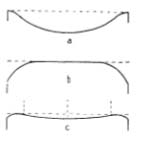
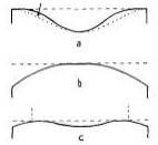
When the knife-edge is at the halfway setting, it may and frequently does happen that instead of the apparent cross section shown in Fig. 39c, shapes like those illustrated in either Figs. 42c or 43c are seen. It is apparent from these shapes that neither of the mirrors represented is a paraboloid, and the centers of curvature of their 70-per-cent zones are displaced. While in either case it is possible to cause the shadow boundaries or apparent crests to land on the 70-per-cent zones by positioning the knife-edge at these displaced centers of curvature, the setting will not be exactly halfway between the centers of curvature of the edge and center zones, nor will the apparently depressed parts of the mirror be at the same apparent level.
Other possible defects are too great a width of the curves at the 70-per-cent zone and insufficient breadth of the central trough, or a condition that is the opposite of this. These errors may escape the observation of the unpracticed eye at the halfway setting of the knife-edge, but their detection should be made possible by the discrepancy in the breadth of the central plateau in Fig. 39b.
Location of the center, 50-per-cent, and 70-per-cent zones should not be left to guesswork. The zones and the center of the mirror can be exactly marked, just prior to testing, with tiny drops of ink deposited on the mirror’s surface from the end of a toothpick. When the mirror is set up for testing, the diameter along which the ink-spots lie should be in a horizontal plane; the spots will be conspicuously revealed by diffraction.
In all this shadow testing, no zonal irregularities should be visible; the shadows must flow smoothly from one zone to another. The depth of shading is not great, and so delicate are the transitions from highlight to shadow that it is difficult to reproduce them faithfully in the drawings. A mirror having the same contrasts as depicted in Fig. 39 would be slightly overcorrected, possibly bordering on the maximum allowable tolerance. Every effort must be made to bring the figure within these tolerances, and, in addition, you should strive for the ultimate in performance by bringing your mirror as close to a paraboloid as patience and knife-edge measurement will permit.
|
|
Testing at Focus
A more positive test than the one just described is made at the mirror’s focus, using parallel light. The set-up for this test is shown in Fig. 40. The mirror and a silvered or aluminized optical flat are aligned with their axes coincident. (A perforated flat is used in this arrangement, although a small prism or diagonal could be centrally placed before an unperforated flat at a 45° angle, and the pinhole and knife-edge moved around” to the side.) Rays from the illuminated pinhole, which is placed exactly in the focal plane, are reflected, parallel, from the paraboloidal mirror to the flat. Thence they return to the mirror, still parallel just as if they had proceeded from a star. The mirror reflects these rays to a point image in the focal plane, and when the knife-edge cuts into that image, the mirror is seen to darken evenly and instantly, just as does a spherical mirror when tested at its center of curvature.
The accuracy of this test is further amplified by the double reflection from the mirror. The flat used must be accurately plane to within 1/10 wave length of light, so it is not a test that the average amateur is likely to employ. But it would be interesting to make the test with your finished telescope on a star, such as Polaris, which is stationary enough for the purpose. Get the star centered in the field, remove the eyepiece, and see if the mirror “blacks out” as a knife-edge is cut slowly across the focal plane.
Test for Astigmatism

In testing for astigmatism, the image of the pinhole should be returned as closely as possible to the source, and in the same plane. This avoids the possibility of any erroneous shadow appearances. If the knife-edge is vertical, any shadow movement at any setting should be in a horizontal direction; that is, if the mirror is considered to be the face of a clock, shadows should approach from the directions of 3 o’clock and 9 o’clock only. Starting with the knife-edge either well inside or well outside of focus, and shifting it gradually and smoothly to a similar distance on the opposite side of focus, observe carefully for shadow approach from any other “o’clock.” All shadow movements should be symmetrical about the horizontal diameter. Test on three diameters.
Parabolizing Strokes
The purpose now is to convert the apparent cross section of the sphere (Fig. 31c) into the apparent cross section of a paraboloid, and as this will be done by removing glass from the center of the mirror, the apparent cross section to be arrived at is the one at a, Fig. 39. Obviously, if the latter shape is seen on the mirror at some knife-edge setting (the center of curvature of the edge zone), the shapes b and c will also be found at appropriate settings, and the parabolizing will have been accomplished. Any stroke or combination of strokes that will progressively deepen the mirror into that shape may be used. Before proceeding, the lap should be hot-pressed into absolute contact with the spherical mirror, and about a half-hour allowed before commencing the figuring strokes. A similar procedure should be observed at any stage of the figuring, if the mirror has been removed from the lap for test, or for some other reason.
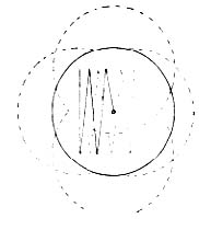
In general, a narrow zigzagging W stroke gives excellent results. This stroke should carry the mirror from a centered position on the lap to about 1¾” overhang on one side, back across the center to an overhang of 1″ on the other side, and thence back to center, where the mirror is given a slight rotation, and the sequence repeated from a new position. Too many strokes taken at one position may cause the surface to become astigmatized. After circling the stand once, test the mirror to locate, if possible, the position of the shadow crests. If they are found too close to the center of the mirror, the stroke length or extent of overhang should be reduced. If too far out, the stroke length or the overhang should be increased. The temper of the pitch will determine the extent of stroke length, which may have to be varied somewhat from the nominal figures given above. The harder the lap, the longer the stroke may be. Fig. 41 shows the positions of the mirror at the extremities of the recommended strokes, and the zigzag line is the course traversed by the center of the mirror. The blending action of this stroke is capable of producing a beautiful paraboloidal surface. By proper manipulation, the degree of correction in any one zone can be varied at will, within limits, provided care is taken to prevent disfigurement elsewhere through deformation of the lap.

Too short a stroke will produce apparent shapes like those in Fig. 42. Note that the crests in c are too far out. Note also that practically all of the correction lies in the outer zones, the center being flat and undercorrected. Unless this is discovered and the stroke lengthened before the correction amounts to more than about 0.05″, overcorrection will probably develop by the time the crests have been moved in to the proper position.
If too long a stroke is used, shapes like those in Fig. 43 will result. Here the center zone has received most of the correction. Although knife-edge measurements may show the full correction to be present, the edge zone is undercorrected, or flat, and the crests are too far in. It is possible to alter this figure to a paraboloid by removing glass from the zone indicated by the arrow at a, down to the dotted curve, where the paraboloid is presumed to lie. In attempting this, a stroke of little more than one-third length is used, with the undercorrected zone overhanging the edge of the lap. With local pressure applied at that point, and a blending action introduced by varying the overhang between that point and the mirror’s edge, successful correction can often be achieved.

Despite the tyro’s best efforts, he will seldom be able to measure the full amount of correction on his mirror, so if the shadow locations are good, it is advisable to call the job finished when the measured correction is about 0.07″ or 0.08″, as there is an excellent probability that the full correction is there anyway.
If the edge has suffered slightly through use of the long strokes, it can be improved or restored by grinding the mirror face down with light pressure on a large piece of plate glass, using No. 305 emery and water for about 15 or 20 seconds. This will grind flat an edge area about 1/40″ wide, and will result in a light loss of about 11/2 per cent, but with a beneficial gain in darkness of field. Flush the mirror clean under the tap, dry it, and observe the diffraction ring on the testing stand.
It is seldom that a paraboloid will be achieved on the first attempt. The worker may overshoot the mark and hyperbolize the mirror, or gross zonal errors may occur. If the figure gets out of hand, it should be restored to a spherical shape by methods outlined in the preceding chapter for correcting the hyperboloid. Through failure, which the novice must be prepared to experience, not once, but several times, you are finding out what not to do, and your judgment and skill in figuring are improving with practice. After the third or fourth trial, the figure obtained will be decidedly superior to what you might have accepted on the first try.
Aluminizing
It is best to defer the aluminizing until the cell and other tube parts have been completed; then the mirror and diagonal can be coated at the same time. In Chapter 16, aluminizing and care of the optical parts are treated in detail. Any but a perfect job of aluminizing should be rejected. If you are willing to go to the trouble and expense, it is a good idea to have the aluminized mirrors, especially the secondary, given a coating of magnesium fluoride — the same as is applied to the surfaces of lenses to reduce reflection losses. This gives a hard, durable surface that will withstand considerably more cleaning than the softer aluminum, without affecting its reflective qualities.
