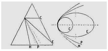
As mentioned in the first chapter, the mirror must have a paraboloidal figure in order that all rays entering the telescope parallel to its axis will converge to meet in a single point in the focal plane (Fig. 10b). It was also stated that a spherical mirror might be altered into that figure in any one of three ways. But not the same size of paraboloid would be derived in each case, although, like spheres, the shapes of all paraboloids are the same.
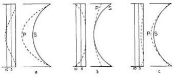
The dotted curves in Fig. 35 represent the paraboloidal surfaces that could be obtained from the same spherical mirror by the three methods. At a, the bulk of glass is removed from the central zones, tapering down to zero at the edges. The paraboloid thus obtained has a slightly shorter focal length than the original spherical surface; the new focal length is equal to one half the radius of curvature of the deepened central zone. Of the original sphere, only an extremely narrow edge zone remains as part of the paraboloid. In mirror work, this is the usual method of parabolizing, done by polishing with the mirror face down on the full-sized lap.
In b, the bulk of glass is removed from the edge zones of the sphere, tapering down to zero approaching the center, where the original sphere merges with the central zones of the paraboloid. In this case there is no change in focal length, as the central zone may be regarded to have been untouched in the operation. An equal amount of glass is removed by this method, but because the work has to be performed with the lap on top, inevitably leading to turned-down edge, it is seldom attempted.
|
In c, glass is removed from both edge and central zones of the sphere, its 70-percent zone (a zone the radius of which is 70 percent of that of the mirror) remaining as part of that paraboloid. The least amount of glass is removed by this method, which also has to be performed upside down, but with a small polisher, used locally. In this operation, the focal length is lessened by half the amount of reduction made in a.
Of course, the mirror sections represented in Fig. 35 are enormously large by comparison with our 6-inch f/8, which occupies so small a portion of the paraboloidal surface (see Fig. 37) that it and the sphere are indistinguishable from each other by any ordinary means of measurement. In the graphs at the left of the diagrams, however, the departure from the sphere, measured in millionths of an inch, is scaled to the apparent magnification of about 100,000 obtained with the Foucault test. Note that the differences at a and b are identical — amounting in the case of a 6-inch f/8 mirror to 11.4 millionths of an inch.
The Reference Spheres
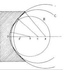
To restate the foregoing, the same paraboloid can be produced from three different spheres of appropriate radius, as shown in Fig. 36. The largest sphere, A, is converted into the paraboloid by deepening it at the center. The smallest sphere, B, is altered by wearing away glass around the edge. The center of this sphere, b, is also the center of curvature of the central zone of the paraboloid, the focal length of which is equal to Pb/2, or PF. By wearing away glass at both edge and central zones, the third sphere, C, is changed to the paraboloid, its 70-percent zone being all that remains of that sphere.
It is thus seen that, by whatever means a paraboloid is produced, there are three spheres of reference with which the optician can test the figure of the mirror’s surface. There are an infinite number of other spheres, of course, but the three described are all that need be reckoned with. The distance between the center of curvature (b) of the mirror’s center zone and the point of intersection with the axis of the normal to any other zone is equal to r2/2R where r is the zonal radius, and R is the radius of curvature of the central zone. For a 6-inch f/8 mirror, the value for the edge and central zones is 0.047″ (a and b, Fig. 36), the same as the mirror’s sagitta. The center of curvature, c, of the 70-per-cent zone is located exactly midway between points a and b.
|
|
Now, by locating the center of curvature of each zone, and measuring the distances between them, we can determine by comparison with the values of r2/2R how closely the figure of the mirror approaches a paraboloid. In the application of this formula, however, both pinhole and knife-edge would have to be moved together. In practice, it is customary to have the pinhole remain stationary and to move the knife-edge only. In this case, the distances between the points of intersection with the axis (of the rays reflected from the several zones) will have been doubled. The formula then to be applied in determining the length of knife-edge travel is r2/R.
Although the points of intersection thus obtained (a, b, and c, Fig. 39) no longer mark the centers of curvature of the respective zones, this convenient expression will continue to be used in their connection. Theoretically, the stationary pinhole should be placed exactly at or alongside the center of curvature of the central zone, but no error is introduced as long as it is somewhere in the vicinity (see Chapter 6, How to Use the Foucault Device). An advantage of thus doubling the knife-edge travel is that the error percentage is halved. The computed value of the r2/R formula (distance ab, Fig. 39) is known as the correction of the paraboloidal mirror, which for the 6-inch f/8 is 0.094″. Ellipsoidal mirrors are referred to as under corrected; hyperboloids are over corrected. The paraboloid is a fully corrected mirror, and is the thin division between the two.
Knife-Edge Magnification
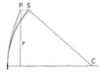
The actual separation between the surfaces of a sphere and a paraboloid of equal focal length, at any zone, when placed with their central zones and optical axes coincident, is equal to r4/8Rs, where r is the zonal radius of the mirror, and R is the radius of curvature of the central zone. For the 6-inch f/8, this is 0.0000114″ at the edge (PS, Fig. 37), equal to half a wave length of light. But under the knife-edge test, this departure is seen apparently highly magnified. A group of my students gave estimates of the apparent depressions of the edge zone of a paraboloidal mirror as seen with the knife-edge placed at the center of curvature of that zone; their values ranged from 1″ to l¼”. If their average, 1 1/8″, is accepted as a reasonable value, it is found that the Foucault device yields an apparent magnification, of course in depth only, of about 100,000.
Now, at a distance of eight feet (the mirror’s radius of curvature), a bump or dent of 1/32″ on a surface is easily seen without optical aid, and its height or depth can be fairly accurately estimated. Assuredly, the presence of a zonal or other surface defect on the mirror, of apparently similar magnitude (the faint marks of the polishing tool that are occasionally seen may be much less), can be detected with the knife-edge and likewise estimated with reasonable accuracy, indicating that errors of the order of three ten-millionths of an inch can be seen.
Surface Tolerance
In 1879 the English physicist, Lord Rayleigh, showed that for practically perfect image formation all of the light emanating from a point in an object (or from a star) must, after reflection or refraction, meet in a point in the focal plane after traversing paths that do not differ by more than one quarter of a wave length of light. This tolerance is known as the Rayleigh limit. Experience has shown, however, that images quite reasonably approaching the same degree of perfection will be obtained if the difference in light path does not exceed twice the Rayleigh limit, or one half of a wave length. (The wave length of yellow-green light, which we may adopt as a standard, is 1/45,000″, or 0.000022″.)
In the case of reflection, the light travels twice through the space in front of the mirror. Therefore, the departure of the mirror’s surface from a true paraboloid may not exceed a quarter wave in order to meet the more tolerant half-wave limit. To this end, the difference between sphere and paraboloid (distance PS, Fig. 37) must be reduced to this amount, or to 0.0000055″.
The 6-inch f/8 mirror must therefore be corrected (under or over) to within 55/114, or approximately 0.045″, of the value of r2/R, so that corrections of between 0.05″ and 0.14″ are tolerable. But because of the probable error of observation, it is prudent to have the measured correction lie within 0.07″ and 0.11″. A mirror corrected to the exact value of r2/R, with a smooth, regular-appearing curve, will perform within the Rayleigh limit, and the finest possible definition will be realized.
Error of Observation
In seeking with the knife-edge the center of curvature of any single zone, which is done through visual interpretation of the shadows cast on the mirror, you cannot, with certainty, repeatedly place the knife-edge within 0.01″ of the true position. A skilled observer can probably halve this error, but with the average amateur, who may make one or at most two mirrors, the error might easily be doubled. Also, assuming that there is no error in the scale, there is nevertheless a possibility of error of 0.01″ in reading it. Of course, where the knife-edge movement is controlled by mechanical means, this latter error should not exist. But as two zones are involved in measuring the mirror’s correction, the worker should be prepared to allow for a total error of 0.02″.
Testing the Paraboloid
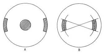
To provide a means of isolating the various zones that are to be tested, and thus to simplify the problem of locating their centers of curvature, it will be necessary to prepare two masks similar to those shown in Fig. 38. These are made of cardboard, each disk being of the same diameter as the mirror. The one at A has a central opening of about l½” diameter, and edge openings about 2″ in length and 0.4″ in width. The openings in the mask at B are ½” wide (¼” on each side of the 70-per-cent zone). A good length to make these mask openings is l½”. The mirror will be tested in three zones; that is, the intersection points of rays from the three zones shown in Fig. 39 are to be sought, and if found where they ought to be, and the curve is smoothly progressive, the mirror may be adjudged a paraboloid. In positioning the testing device preliminary to actual testing, the guide cleat (see Fig. 19) used to guide the longitudinal motion of the knife-edge should, as a matter of convenience, point directly to the vertical diameter of the mirror.
|
In seeking the center of curvature of any zone, it is a good idea to begin by trying with the knife-edge placed well inside, and then outside of that point — bracketing it, so to speak — and then gradually to close in on it from each side. Knowing how the shadows appear on either side of focus, the observer is able to decide more accurately where the exact center of curvature of the zone lies.
Place the mirror on the testing rack with mask A directly in front of and concentric with it. Set up the testing apparatus, bringing the knife-edge block against the guide cleat so that the indicator is over the scale, and shift the whole device about until after repeated trials the knife-edge is at the center of curvature of the zone exposed by the edge openings of the mask. This occurs when the first faint shadows appear simultaneously in each edge opening, and are at the same time of an equal depth of grayness. The comparison should be made not when the zone exposures have darkened, but just as the knife-edge encroaches on the rays proceeding from these openings, and while the most delicately gray shadings that permit proper observation are present. This will call for some nice judgment of contrast, particularly as diffraction around the edges of the openings may have a blinding effect (the trick here is not to look at this diffraction), and your eye must dart from one opening to the other to check for simultaneous appearance of the shadows.
