Diagonal Holder
At this point a full-scale sectional drawing of the eyepiece end of the tube should be made, similar to Fig. 59, showing in detail the diagonal, holder, spider supports, and so forth. The block on which the diagonal rests, B, is a prism-shaped piece of hardwood cut from a square stick of the same width as the diagonal. A ⅜” square-sectioned strip of wood is glued across the base of the hypotenuse face of B, and later one half of it is planed away, making a neat-fitting seat, C, for the diagonal A. The latter is held in place with three pieces of thin sheet brass (Fig. 60), one of which is tacked to the back and the others to the sides of the wooden prism. These brass pieces should first be annealed by heating them over a flame to a red heat and quenching in water. Use a hardwood stick to bend the “ears” of the pieces over the corners of the diagonal. Do not pinch it tightly—there should be a barely perceptible shake to it.
A 1/16″ thick brass plate, D, is fastened to the base of the prism with small wood screws. The small hinge F joins that plate to the 1/g” thick plate E; use either small metal screws or solder in attaching F. The hinge, which can be purchased at any hardware store, may be so stiff as to resist the action of the compression spring G, but it can be completely loosened by applying a pinch of rotten stone or emery and oil to the hinge joint, and working between the fingers for some minutes. A No. 4-36 screw and a compression spring between the plates, opposite the hinge joint, provide adjustment in the angle of deflection.
The plate E screws onto a length of 1/4-20 rod which has been threaded at both ends. A study of Fig. 47 will disclose the fact that the rod, although centered in the lube, should not be centered in the plate, but offset slightly. Failure to take this into account means only that the fully illuminated field of view, circular in outline, will not be concentric about the optical axis, but as the offset in the 6-inch f/8 telescope amounts to only about 1/25″ it can be ignored. However, if a totally reflecting prism is used in place of the diagonal, it is correct to center it.
 to wood prism B.")
The nuts I and K should first have been screwed on, and the joint at I should be soldered. The nuts K and L lock against the central support I, a small longitudinal adjustment being provided to compensate for error in locating the holes for the spider in the tube. N is a small counterweight (that might be omitted) used to remove torque from the vanes.
If ordinary lock washers (not shown in the diagram) are inserted between the nuts K and L and the support I, then after the longitudinal adjustment is effected and the nuts moderately tightened, rotation of the rod H is possible without disturbing the locking mechanism. This is of decided assistance in making alignment of the optical axis with the eyepiece.
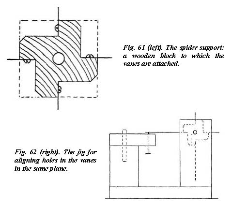
Spider Support
Drill a 1/4″ center hole through a block of hardwood 1/2″ long and cut from the same square stick as was the wooden prism B. Saw it out to the shape shown in Fig. 61. For the vanes cut four rectangular pieces, 1½” x 2⅜”, from sheet metal not less than 0.012″ thick, and attach them with small wood screws to the wood center piece. Holes for attaching the spider to the tube must be drilled in the vanes so that they will be equidistant from the rotational axis of the diagonal and in a plane at right angles to it. This can be done accurately on the lathe, or the special jig shown in Fig. 62 must be made to insure accurate location. Placed in this jig, with the center rod held rigidly between the two side boards, and the spider rotating in a fixed position, each vane will land in turn on the nail point shown. A light tap with a stick will impress this point in the vane. After drilling out the holes thus marked, the vanes should be trimmed to a triangular shape, as shown in Fig. 59.
 |
For holding the spider in the tube, short lengths of ¼” metal rod are used. Four pieces of this rod, about ⅞” long, are threaded for ⅝” of their length; a small hole is drilled through the unthreaded end, which is then slotted longitudinally with a hack saw for fastening to the vanes. (Rather than use rod, 1″ long 14-20 round-head bolts can be bought and their heads sawed off.) Cotter pins may be used to attach these studs to the vanes. The holes in the tube should be about 9/32″ in diameter, all four located exactly in the same plane so that the spider will assume the position shown in Fig. 63, thereby giving access to the adjustment screw of the diagonal.
 |
The inside of the telescope tube, adapter tube, vanes, and all other exposed parts should be thoroughly blackened.
The Saddle
Since the eyepiece of the Newtonian reflector is frequently found to be in an awkward position for observing, it is customary to provide a means of rotating the tube in its saddle or cradle (M in Fig. 9). A good length for the saddle is about 15″. The tube rests in V ways, or the ways may be curved to fit the tube. The center of balance of the telescope must be centered on the saddle. To prevent slipping, two rings of metal, plywood, or thick leather belting (K in Fig. 9) are secured to the tube, flanking the ways; straps of leather or spring brass (L in Fig. 9) hold the telescope to the saddle. A method of attaching bolts to the straps is shown in Fig. 64; metal straps may be riveted directly to the bolts. The bolts enter slotted metal bars fastened to the bottom of the wooden saddle, and extending out about 1″ on either side (see Fig. 9). To reduce friction in rotating, the straps and saddle ways should be lined with felt where they bear against the tube. This material can be held in place with glue or shellac. With such an arrangement, rotation is easy, and when it is time to close up for the night, loosening of the wing nuts allows the straps to be quickly slipped off so the telescope can be removed indoors.
|
|
 straps for securing the telescope to the saddle.")
Optical Alignment
Strap the empty tube in its saddle and clamp that to the workbench so that it cannot be moved. Set up a lamp or other light source about 48″ from the eyepiece end of the tube, and on its extended axis. Then stand a white cardboard screen, having a 1/8″ hole in it, directly in front of the lamp. Make two cardboard disks, each with a 1/8″ center hole, and fit one into each end of the tube. By sighting through the holes, adjust screen and lamp to bring all three holes in line.
Into each end of the adapter tube fit a wooden plug with a 1/8″ center hole. Then a length of 1/8″ rod is inserted through the holes in the plugs. Square the rod exactly with the tube longitudinally by means of the spring adjustments on the blocks, checking with a square and rule or dividers. Then push the rod in until it has gone past the center of the telescope tube, and, by sighting through the end of the tube, see if the rod has cut off the light. The adapter must be adjusted until the light is cut off by the rod, then again square the rod with the tube longitudinally, as this first adjustment will no doubt have been disturbed.
Repeat the tests until you are certain that the adapter is square in both planes, after which remove the rod and plugs from the adapter, and also take the cardboard disk from that end of the telescope tube. Now put in the spider, being careful not to disturb the position of the tube, and center it by sighting through the other end of the tube. When the spider is centered, remove the diaphragm from the mirror end and put in the cell containing the mirror. An image of the hole in the cardboard screen will probably be seen somewhere on the screen, and by manipulating the adjusting nuts on the cell make this image fall directly back on the hole. The axes of tube and mirror have now been made coincident and at right angles to the axis of the adapter tube.
All that remains is to insert the diagonal and to bring the deflected axis of the mirror coincident with the axis of the adapter. Fix a small diaphragm of some sort, having a 1/16″ hole at its center, over the eyepiece end of the adapter. Placing your eye close to this opening, you will see the walls of the adapter tube, a reflection of the mirror in the diagonal, and in this a reflection of the spider and diagonal, and also a reflection of the hole through which you are peering. These reflections must all be brought concentric with each other, and if the preliminary work has been carefully done, the three adjustments that are provided on the diagonal will be sufficient for the purpose. This last operation is most easily performed outdoors with the telescope pointed at the daylight sky.
The Finder
Usually attached to the reflecting telescope is a small refractor, of short focal length and low power and possessing a wide angular field of view. For a 6-inch telescope, the finder may be anywhere from 1″ to 2″ in aperture, and 6″ to 12″ in focal length. When it is aligned axially with the mirror, the sighting of celestial objects is made easy by reason of the finder’s large field.
Crosshairs or wires are usually stretched diametrically in front of the field lens of the finder eyepiece, exactly in the focal plane of the objective and intersecting at right angles in the center of the field of view. When the object sought has been brought to the intersection of the crosshairs in the finder, it will then also be in the center of the field of view of the mirror. Instead of cross-hairs, a reticle, consisting of a thin glass disk on which cross lines have been etched, may be more simply installed.

- Fig. 65. Plan (about 4/9 actual size) of image formation in telescope and eye. The refractor consists of a 1.7″ objective, focal length 9″, and a Ramsden eyepiece of 1½” focal length, giving an apparent field of 36°. Magnification is 6x; the exit pupil is 7 mm. in diameter; and the real field of view is 6°. The latter is rather more than is desired in a finder, and for this purpose the focal plane (pf) might be stopped down to about half its present size, or an eyepiece of shorter focal length can be substituted.
Crosshairs or wires are usually stretched diametrically in front of the field lens of the finder eyepiece, exactly in the focal plane of the objective and
intersecting at right angles in the center of the field of view. When the object sought has been brought to the intersection of the crosshairs in the finder, it will then also be in the center of the field of view of the mirror. Instead of cross-hairs, a reticle, consisting of a thin glass disk on which cross lines have been etched, may be more simply installed.Fig. 65 is representative of the small telescope that is used. From the stores of salvaged war surplus goods, achromatic objective lenses of 1″ to 2″ aperture and 6″ to 12″ focal length can be picked up at very low cost, as can the lenses for the finder eyepiece.
More simply, though, as there is little need to be critical of aberrations, the objective lens might be an ordinary convex spectacle lens and the eyepiece a plano-convex lens of 1″ to 2″ focal length. But as a field at least 3° or 4° in diameter is desirable, a field lens (see discussion in next chapter) of similar focal length should be placed in or near to the focal plane of the objective lens. Means of focusing the eyepiece can be dispensed with, the lenses being secured in a single tube, a la Galileo, with the eye lens fixed at best focus for a star.
Perhaps the most suitable location for a finder is that occupied on the 8-inch telescope in Fig. 96, where the two eyepieces are in proximity. Often a star diagonal (right-angle prism) is incorporated in the body of the finder, deflecting the optical axis of its objective lens at right angles, so that both eyepieces may be brought adjacent to each other. In this way the observer looks in the same direction in using either instrument, but opinion seems to have it that it is preferable for the purpose of finding to look in the direction of the object. (In the telescope in Fig. 96, the weight of the eyepiece holder and the finder, both made of heavy bronze parts, necessitated the addition of the counterweight on the opposite side of the tube, to restore the center of gravity to the tube’s axis. A sliding adjustment of the weight was provided to compensate for slight error in locating the balance about the declination axis.)
So that the finder can be aligned axially with the main telescope, it is usual to suspend it inside of two rings, and clamp it there by means of screws, in a manner similar to that in which the shafting is shown centered in the fitting in Fig. 80. The rings can be cut from large-diameter tubing, and posts for attaching to the main telescope soldered to them. The minimum height of the finder’s axis above the telescope tube should be about 2″.While the finder is a convenience, it is by no means an essential accessory on a telescope of the size we are making, especially if setting circles are to be attached to the mounting. But if the instrument is to be portable, circles will have little practical value, and should be omitted. Then the telescope may be aimed as though it were a gun, at the approximate spot in the heavens where it is desired to observe; a brief search in that vicinity will usually bring the object sought into the field of a low-power eyepiece. A pair of sights, such as axially aligned protruberances on the tube, may facilitate the above procedure. However, many observers will appreciate the usefulness of a finder, and although it is desirable to encumber a portable telescope as little as possible, the added weight of a small refractor need not be objectionable.