The Mirror Cell
The wooden cell described here is easily made and permits of ready adjustment. The materials required are: two well-seasoned hardwood boards, one 6″ square and: ¾” thick, and the other about 8″ square and 1″ thick; three WSO round-head stove bolts, 3″ long, and nine washers to fit; three very stiff compression springs, ¼”to ½”long and large enough in diameter to fit freely over the stove bolts; three ¼-20 wing nuts; three 10-24 round-head machine screws %” long: three 10-21’s 1″ long. Clips for securing the mirror to the cell can be cut from brass angle shapes obtainable from the 5 & 10.
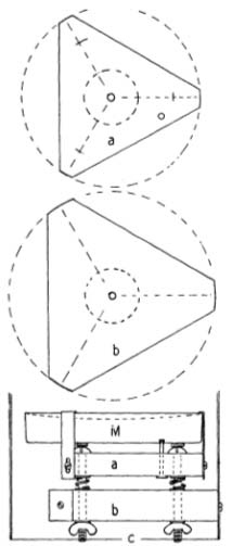
On the small board inscribe an equilateral “triangle” in a (V circle as in Fig. 57a. Mark the holes for the stove bolts 2.1″ from the center. On the large board lay off the equilateral “triangle” inscribed in a circle of the same diameter as the inside of the tube (Fig. 57b). Drill center holes in each board, the size of a dowel stick or bit of rod that may be on hand, and saw out the triangles; the corners must be cut to exactly the proper radius and be made concentric. Center the triangles on each other by passing the dowel stick or rod through the center holes, clam]) them, and drill out the stove-bolt holes with a ¼” drill. Before separating the triangles, mark them so that they can be returned lo the same respective positions. Then enlarge the holes in triangle b with a 9/32″ or 5/16″ drill to permit free movement over the stove bolts. Drill holes in the angle clips with a No. 12 drill, and elongate them slightly with a small round file. The clips are fastened to the corners of triangle a with the ⅝” screws, first drilling holes for them into the wood with a No. 24 drill. The machine screws will have ample holding power and are preferred to wood screws where frequent removal may be necessary. Before placing the mirror in the assembled cell, file a small flat area on the heads of the stove bolls, and cement to them thin pieces of felt, cork, or leather, on which the mirror will rest. The small dotted circles in the center of each triangle may be cut away with a scroll saw to give ventilation.

The mirror must not be pinched in its cell, as even slight flexure may distort its figure. But if not secured in some manner, it is free to rotate, and occasionally does so from being jarred, throwing its axis out of alignment. To prevent this, a small hole into which the point of a nail or screw may fit should be drilled into the back of the mirror. A nail can be used for a drill. Cut the head off squarely, and insert the pointed end in the drill press. A hole about 1/16″ deep, drilled with No. 120 carbo and water, will be ample. It can be seen from Fig. 57 how the mirror is then anchored. Finally, blacken all interior parts of the cell with a flat black enamel.
The cell is held in the tube by the three 1″ screws, entering triangle b through the tube sides. To bring the holes in the tube in the same plane, wrap a large sheet of paper around it with the paper’s straight edge overlapping in that plane, and mark off the locations of the holes there, 120° apart. After the holes in the tube are made, drill a hole in one corner of the wooden triangle and insert a screw into it through the tube. Steadying the assembly with one hand, bring a second corner opposite one of the other holes in the tube, and mark through the hole on a center line which has previously been inscribed on the triangle. On removing the triangle, this second hole is now drilled, after which the triangle is replaced in the tube, engaged by two screws this time, and the third hole spotted and similarly drilled. In this way, the holes in the tube are transferred accurately to the corners of the triangle.
A refinement which is not essential will provide a much more stable and durable bearing area. After the holes are located in the triangle, drill them out to 1/4″ size; then insert short lengths of metal rod of that diameter which have first been centrally bored out and tapped for No. 10 screws.
A word of caution is necessary about the making of the wooden triangles. Be very precise about cutting off the corners to the exact diameter, and be sure they are kept concentric, or the mirror cannot be centered in the tube and the efforts to simplify alignment will have been wasted. For easy collimation of the mirror’s axis, the cell should be oriented in the tube as shown in Fig. 9, left.
The Tube
This may be made of almost any material, sheet metal, cardboard, plywood, aluminum, or bakelite tubing, or it may be of the skeleton type, although the latter is not recommended except for large telescopes. Rolled sheet metal is perhaps most frequently used. Aluminum (1/16″ wall) and bakelite 1/8″ wall) are light and accurately round. The cardboard tube around which rugs are rolled is excellent if first doused inside and out with two or three coats of shellac. A tube of any of these materials will provide all the strength and stiffness needed for the telescope.
The tube’s length should he about 52″, equal to the focal length of the mirror plus whatever is needed to enclose the cell. To locate the eyepiece opening, mark a point on the surface of the tube 41½” from the plane in which the surface of the mirror will lie, and with that point as a center describe a circle of ¾” radius. (The distance of 41½” assumes a focal length of 48″, a tube diameter of 7″, and a distance of 3″ outside of the tube for the focal plane. However, see paragraph on page 109 if the tube is accurately round.) Now drill numerous holes around this circle with a small drill, not larger than 1/8″, and cut out the hole which, when smoothed up with a file, will be about 1⅝” in diameter.
|
|

|
Eyepiece Support
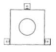
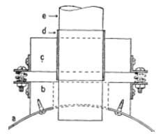
A block of hardwood (maple preferred) 3″ square and 1″ thick should then be taken to a pattern maker and shaped to fit the curve of the tube, and also to have a 1⅝” hole bored squarely through its center. This block is fastened over the opening in the side of the tube as shown in Fig. 58. At the same time have another block of similar dimensions (except see second paragraph below) bored out to receive a brass bushing having an inside diameter of 1 5/16″. This bushing should be about 1½” long, with a wall thickness of either 1/16″ or 1/8″, and must fit tightly into the block. It should be sealed in with shellac. It will be much better if the bushing has a flange at one end.
|
|
The eyepiece adapter tube, which should telescope snugly and smoothly into the bushing, is a piece of brass tubing about 4″ long, II/4″ inside diameter, with a 1/32″ wall. One end should have three or four longitudinal slots cut into it for a length of about 1″; this can he done with a thin-bladed hack saw. The walls can then be sprung in with slight finger pressure, insuring a firm grip on various eyepieces. Quite often, the adapter tube fits too tightly in the bushing, and some filing and abrading with emery paper must be resorted to in order to effect a smooth fit. A machinist can do this job quickly on a lathe, holding the tubing on a mandrel. The two wooden blocks are joined as shown in Fig 58, with three compression springs between the matched angles to provide an adjustment that will bring the deflected axis of the mirror and the axis of the adapter tube coincident.
If the tube is accurately round, as, for example, a seamless aluminum tube, it will be possible to dispense with the spring adjustments described. In this case only a single block of wood at least 1¼” thick is used. One surface is milled to fit the curve of the tube, and a center hole, of a size to accommodate the bushing, is bored radially to this curve, automatically bringing the adapter square to the tube. Even if the adjustment is not quite accurately made mechanically, it can be corrected by inserting shims where needed between the block and the tube. Another advantage of this arrangement is that it makes possible placing the diagonal about %” closer to the focus; as this would alter many of the foregoing dimensions, plan the change carefully if you decide to make it.

